filmov
tv
FSK Modulation and Demodulation

Показать описание
An explanation about FSK Modulation and Demodulation.
In this video, Gregory explains the full topology of an FSK demodulator, showing how the bitstream is recovered, how time is synchronized and frequencies offset are compensated.
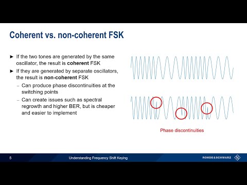
FSK modulation encodes the data in shifts of frequency. In the case of binary signaling, two different frequencies are used, representing 0 and 1.
The process of demodulation is done using two NCOs - Numeric Controlled Oscillators - and average filters, actually implementing a sample-by-sample DFT in real-time.
The energies at the two different frequencies are compared to determine if the data bit is a 1 or a 0.
The continuous recovered bitstream is sampled with a NCO running at the baudrate and a Gardner Time Error Detector in conjunction with a PI controller corrects the sampling interval/point.
Frequency offset are compensated using a slow time-constant servo-loop that equalize average energy of the sampled points.
Support the channel, become a Patron!
A related video about Clock Recovery PLL:
Learn how a Costas Loop demodulator works for PSK modulations:
Article about how DFT works:
00:18 - Introduction
03:36 - Overall demodulator topology
06:15 - Detecting energy without filter (DFT)
10:38 - Quadrature detection topology
13:24 - Time Recovery/Synchronization
16:55 - Offset compensation/Carrier Recovery
Subscribe to receive more videos.
In this video, Gregory explains the full topology of an FSK demodulator, showing how the bitstream is recovered, how time is synchronized and frequencies offset are compensated.
FSK modulation encodes the data in shifts of frequency. In the case of binary signaling, two different frequencies are used, representing 0 and 1.
The process of demodulation is done using two NCOs - Numeric Controlled Oscillators - and average filters, actually implementing a sample-by-sample DFT in real-time.
The energies at the two different frequencies are compared to determine if the data bit is a 1 or a 0.
The continuous recovered bitstream is sampled with a NCO running at the baudrate and a Gardner Time Error Detector in conjunction with a PI controller corrects the sampling interval/point.
Frequency offset are compensated using a slow time-constant servo-loop that equalize average energy of the sampled points.
Support the channel, become a Patron!
A related video about Clock Recovery PLL:
Learn how a Costas Loop demodulator works for PSK modulations:
Article about how DFT works:
00:18 - Introduction
03:36 - Overall demodulator topology
06:15 - Detecting energy without filter (DFT)
10:38 - Quadrature detection topology
13:24 - Time Recovery/Synchronization
16:55 - Offset compensation/Carrier Recovery
Subscribe to receive more videos.
 0:21:25
FSK Modulation and Demodulation
 0:08:55
Understanding Frequency Shift Keying
 0:25:58
Frequency Shift Keying FSK (definition, waveform, multi level FSK, Bandwidth & Modulation) Expla...
 0:05:30
Digital modulation: ASK, FSK, and PSK
 0:06:49
FSK Modulation and Demodulation (MATLAB simulink)
 0:16:13
Communication Engineering - Frequency Shift Keying (FSK)
 0:28:20
FSK MODULATION AND DEMODULATION
 0:07:26
Understanding Modulation! | ICT #7
 0:17:45
FSK Modulation - Demodulation || Lab Experiment || Frequency Shift Keying || Practical || Modulation
 0:06:25
Frequency Shift Keying (FSK) Modulation and Demodulation
 0:11:56
Frequency Shift Keying (FSK) | Modulation & Demodulation
 0:10:54
Visualising Digital Modulation: ASK, FSK, BPSK, DPSK, QPSK and QAM
 0:12:00
What is Modulation ? Why Modulation is Required ? Types of Modulation Explained.
 0:01:25
Frequency Shift Keying (FSK)
 0:03:51
FSK Modulation & Demodulation
 0:09:43
DC#44 Binary Frequency Shift Keying (BFSK) signal Generation, coherent & non coherent detection ...
 0:10:03
FSK modulation | N9310A and N9320B | Keysight Technologies
 0:21:25
Demodulating SAME FSK with audacity Part 1
 0:03:31
LAB 6 FSK MODULATION AND DEMODULATION(GROUP 15)
 0:00:38
FSK MODULATION DEMODULATION TRAINER KIT VINYTICS
 0:19:37
FSK Modulation and Demodulation
 0:01:01
FSK ( Frequency shift keying) modulation and Demodulation.Demodulation using envelope detector.
 0:26:04
Frequency Shift Keying Modulation and Demodulation Lab Experiment
 0:28:01
FSK Modulation/Demodulation
Комментарии