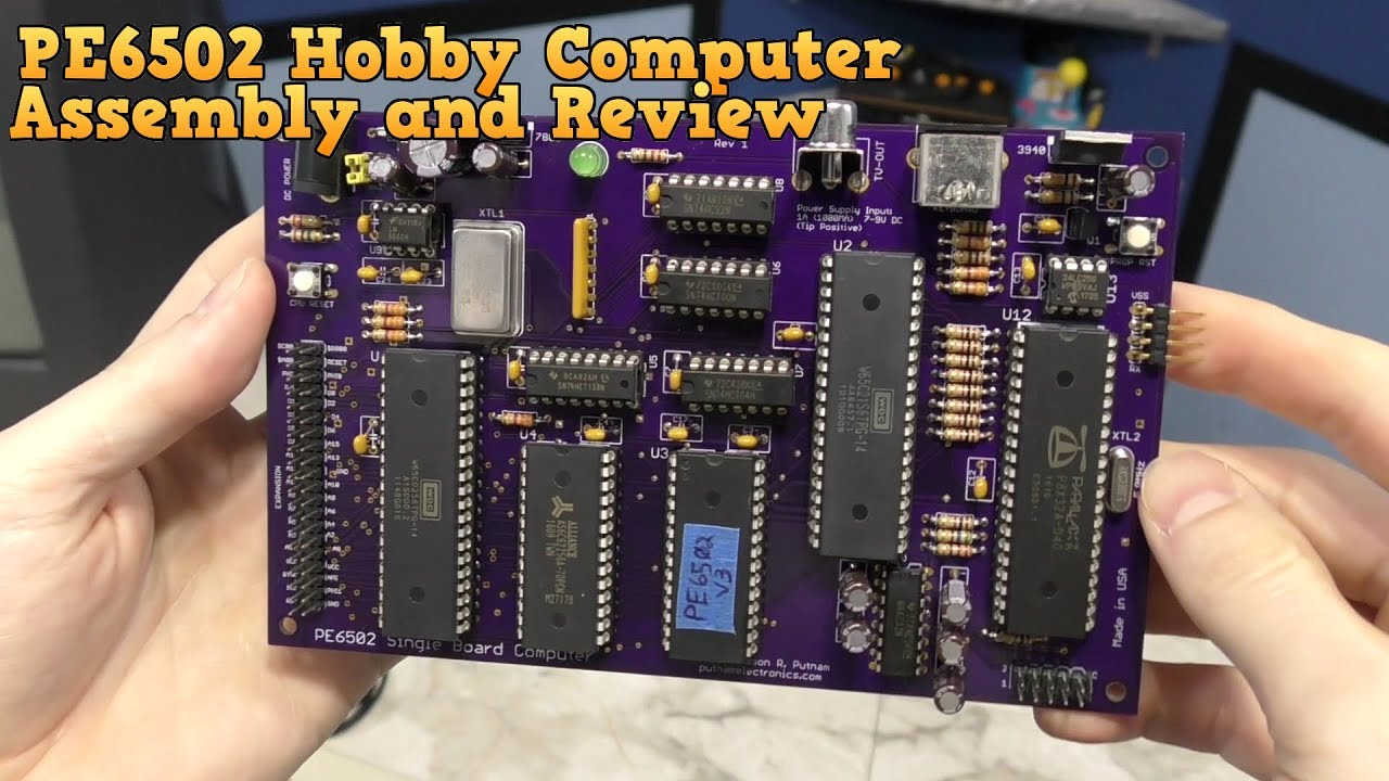
Assembly and Review - PE6502 Hobby Computer

preview_player
Показать описание
Support this channel on Patreon

Visit my website for cool gear:

For more information on the PE6502 computer, visit:

In this episode I build the Putnam Electronics PE6502 hobby computer and test out it's capabilities!
Рекомендации по теме
Комментарии
Автор

When I joined the Army in 1974 I wanted to be an electronics technician. But due to my color blindness I ended up in a combat unit. I’ve always thought I couldn’t do electronics but I started with Arduinos and now I am assembling boards, and doing other things. That is to say, I am glad to have run into your video and see what you did. I am very inspired and thank you.

jimsmith
Автор

"I'd probably try to design it myself but..."


And here you are almost 2 years later, designing such a thing yourself, and having a team helping out making it a reality.

cstuff
Автор

Who else agrees that when the chips are inserted into the sockets its super satisfying

aydenstockham
Автор

"I'll be impressed when someone builds something like this that can run commodore BASIC"


2 years later


"Fine I guess I'll do it"

dthompson
Автор

Yes, a big part of the appeal in building your own kits like this is the experience itself. I'm an amateur at this hobby myself, but it's always exciting to spend an hour on building up a board, plugging in the power, and having things come to life. Honestly, I've been burned, I've accidentally broken off parts, I've even been temporarily blinded by an errant solder splash, and I've had some failed kits. But, it's always fun to take a crack at one, and I'm considering picking up one of these more complex boards.

LorenHelgeson
Автор

As a professional electronics engineer, let me tell you: your tutorial is GREAT. I can't do better. Camera and macros are great. Audio dubbing: perfect. Overall very high quality. BIG thumbs up. As always. Max

MaxKoschuh
Автор

I joined the New Zealand Army in 1979 as an apprentice radio tech. There were about 6 of us that started that year. Early on in the programme we were learning resistor colour codes and all of us had the same resistor in our hands. The instructor asked one of the guys the colours on his resistor and he came up with something completely different to what we all had. Within a week, he was an apprentice vehicle mechanic.

spudpalmy
Автор

I think this board has more capability than used yet. The Parallax Propeller is a bit of a beast in this system, it has 8 32bit cores (called "cogs") and could easily handle more complex VGA (RGB) graphics.

chtech
Автор

I've watched this video several times and I don't mind seeing it again because the quality of his work is inspiring. It's well organized and the filming of the tiny parts is very good.

billchatfield
Автор

That 6502 is not made by Western Digital, but by Western Design Center, hence the WDC in the chip.

sergioaguayogarciara
Автор

During this hard time after Hurricane Maria through Puerto Rico, your videos give me some sense of normalcy, keeps me from going insane, thank you.

everybodyhasmine
Автор

2:06 Wow, I didn’t know you were colourblind! You did a great job with the stickers for the mini arcade machines and when you redid the lables for the cartridges

mishumydog
Автор

Удачи и спасибо за проекты. Многие люди цветозрящие не готовы взяться за подобные проекты. Респект Вам!

lerkomsmartgf
Автор

Maybe you could make a text-adventure style version of Tetris... "You see four blocks above you, shaped like an L. It's turned 90 degrees clockwise and falling. " -> "MOVE LEFT AND MOVE LEFT AND DROP BLOCK"

MK-lknc
Автор

For stuff like the resistor pack I use blue tape. Easy on, easy off and it holds the part down. And I've done boards with a few hundred solder joints so no issues there.

kds
Автор

8 bit guy: *Standard troubleshooting steps.*

Me: *START UP, YOU PIECE OF CRAP!*

twistedyogert
Автор

I absolutely love your videos, and this one is no exception. Just a tiny hint for you from someone who has been soldering for 30 years... Try not to put the solder onto the tip first and then onto the joint. Heat the joint by placing the iron tip so it's touching both the lead and the pad, then apply the solder to the other side of the lead and pad, trying not to touch the tip at all. This will ensure a much better quality joint as you are making sure both surfaces are properly heated.

lptf
Автор

Being a kid born in 98 and craving all these 80's and early 90's knowledge and tech makes me love this channel all too much. This is even better, making old tech out of new. Hell yeah.

v
Автор

Excellent, but you CAN change individual characters on the screen despite it not having a memory-mapped display. With a serial display (as in a 'dumb terminal') a character will always be drawn to the right of the cursor, so all you need to do is move the cursor to the point on the screen before you want to display a new character. Cursor control can be effected via 'escape sequences' or 'control sequences'. I used to do this as a programmer in the 1970's onwards. I can't remember many of the control codes, but one which will always stick in my mind is 'control-G' (or '^G') to sound the bell/buzzer or, on serial-port cash registers, open the cash drawer. Some of the old dot-matrix printers, and even some daisy-wheel printers, used to respond to the same codes which allowed you to draw pictures on them.

kevinlawton
Автор

I appreciate the time you take to explain all the steps! Thanks Dave. Great video as always.

magnum