filmov
tv
What Is A Shunt Resistor, How Does It Calculate Current & How To Make One (DIY)

Показать описание
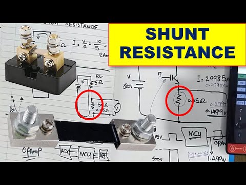
Element resistors, or Shunts, are produced using a solid piece of resistance material. Shunts are commonly used to measure the current output of a circuit. The voltage drop across the extremely lower resistance value can be used to calculate current flow in high current applications.
By measuring the voltage across the shunt and knowing the shunts resistance value, we then can calculate the current I = V / R
___________
Hi, I'm Hamed, an Electrical & Electronics Engineering Student in Leeds, UK. At the time of recording this video I am approaching my third and final year at university.
Stuff You May Have Seen In My Videos
You Can Also Find The Above For Cheaper On Banggood/Aliexpress
 0:11:44
What is a SHUNT? (Used to measure Current) + How to make a DIY version
 0:01:30
What is a Shunt?
 0:02:34
What Is The Purpose of a Shunt?
 0:11:17
How to Make a Shunt Current Sense Resistor
 0:01:54
Measure current with a shunt resistor and DMM voltmeter
 0:01:44
What is a Shunt? - A Galco TV Tech Tip | Galco
 0:12:17
How to choose a shunt resistor
 0:15:30
What Is A Shunt Resistor, How Does It Calculate Current & How To Make One (DIY)
 0:12:46
Voltmeters, Ammeters, Galvanometers, and Shunt Resistors - DC Circuits Physics Problems
 0:19:17
357 SHUNT Resistance, Uses and Working Principle, How to Measure Current using Shunt Resistor
 0:10:20
What Is A Shunt? How They Work. Coulomb Counter Sampler Lithium LiFePO4
 0:05:49
{1147} Understanding Current sense resistor || shunt resistor
 0:02:18
How to test Shunt Current Sense Resistor with multimeter, Current Sense Resistor Working Principal
 0:17:58
A Shunt Regulator Answers to Questions
 0:04:24
Shunt Resistor Current Measurement
 0:02:54
How to Measure DC Current with a Shunt Resistor @ElectricalWiringSchool
 0:22:01
What Is Shunt Resistor? | Shunt Resistor | 99% Technician Nahi Jante Hai
 0:02:57
Datasheet example: current shunt resistor (DC shunt)
 0:01:44
ROHM's High Power Shunt Resistors
 0:01:00
DC Shunt Resistor For Ammeter Voltmeter
 0:12:41
Mas que Raios é um Shunt Resistor? Como fazer um!
 0:21:07
Shunt resistor build for testing parasitic draws
 0:01:47
How to Measure Power Rail Current with a Shunt Resistor
 0:31:02
Shunt Resistor | Use of shunt resistor in PCB | Shunt resistor complete working in AC PCB
Комментарии