filmov
tv
𝐈𝐅𝐃 𝟐𝟒𝟒 𝐊𝐫𝐨𝐦 𝐒𝐜𝐡𝐫𝐨𝐝𝐞𝐫 | 𝐀𝐮𝐭𝐨𝐦𝐚𝐭𝐢𝐜 𝐛𝐮𝐫𝐧𝐞𝐫 𝐜𝐨𝐧𝐭𝐫𝐨𝐥 𝐮𝐧𝐢𝐭 | 𝐂𝐨𝐦𝐦𝐢𝐬𝐬𝐢𝐨𝐧𝐢𝐧𝐠 | 𝐑𝐞𝐚𝐝𝐢𝐧𝐠 𝐨𝐟 𝐭𝐡𝐞 𝐩𝐚𝐫𝐚𝐦𝐞𝐭𝐞𝐫𝐬
Показать описание
𝐈𝐅𝐃 𝟐𝟒𝟒 𝐊𝐫𝐨𝐦 𝐒𝐜𝐡𝐫𝐨𝐝𝐞𝐫 | 𝐀𝐮𝐭𝐨𝐦𝐚𝐭𝐢𝐜 𝐛𝐮𝐫𝐧𝐞𝐫 𝐜𝐨𝐧𝐭𝐫𝐨𝐥 𝐮𝐧𝐢𝐭 | 𝐂𝐨𝐦𝐦𝐢𝐬𝐬𝐢𝐨𝐧𝐢𝐧𝐠 | 𝐑𝐞𝐚𝐝𝐢𝐧𝐠 𝐨𝐟 𝐭𝐡𝐞 𝐩𝐚𝐫𝐚𝐦𝐞𝐭𝐞𝐫𝐬
ℙ𝕝𝕖𝕒𝕤𝕖 🙏 𝕃𝕚𝕜𝕖 👍 𝕊𝕙𝕒𝕣𝕖 🌀 𝕊𝕦𝕓𝕤𝕔𝕣𝕚𝕓𝕖 👆
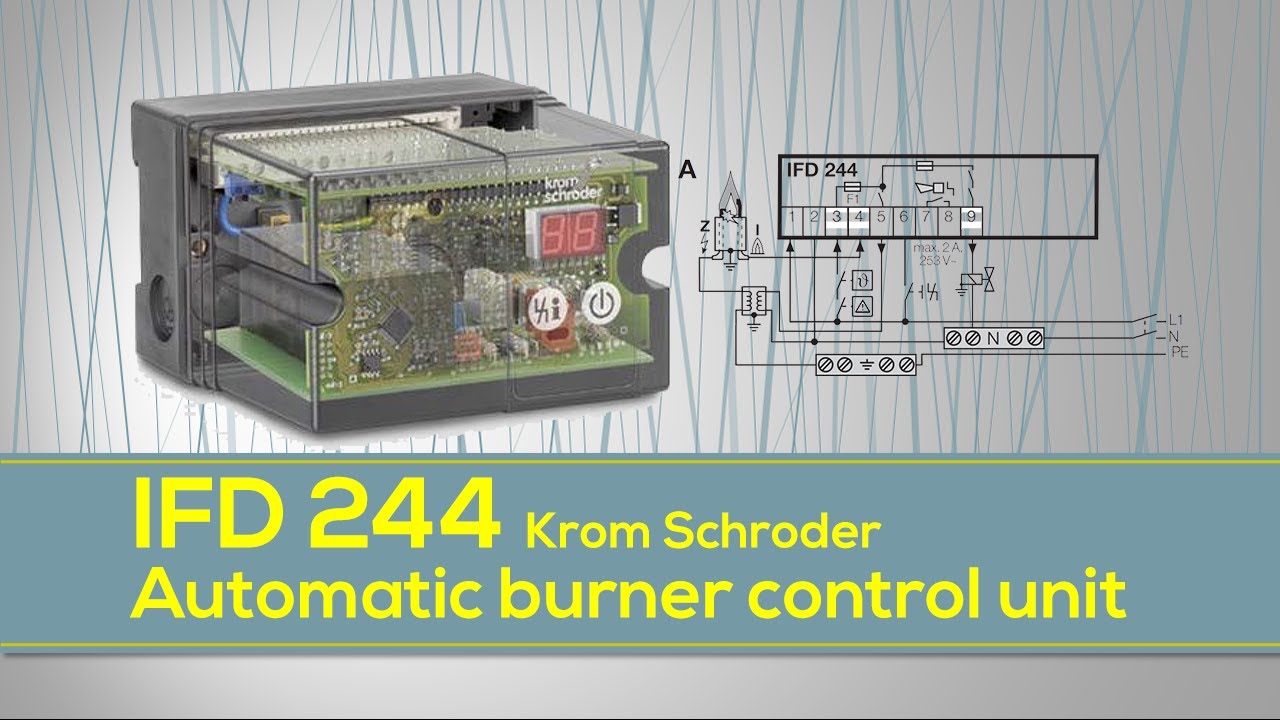
IFD 244
Gas burner monitoring with an ionization electrode. For grounded systems. With restart after a flame failure.
Commissioning
➔ During operation, the 7-segment display shows the program status:
00 Start-up position
01 Waiting time
02 Safety time on start-up
04 Operation.
1. Close the manual valve!
2. Switch on the system.
3. Apply voltage to terminal 1.
4. Check the electrical installation.
5. Switch on the IFD.
➔ The display indicates 00.
➔ The IFD retains its switch position when the voltage is removed from terminal 1.
6. Start the program for the burner: apply voltage to terminal 3 – the display indicates 0 1.
➔ ϑ signal minimum ON time (terminal 3):
IFD..-3: 8 s
IFD..-5: 10 s
IFD..-10: 15 s
The times must be at least this long, otherwise the automatic burner control unit cannot monitor the burner.
➔ Gas valve V1 opens, the burner ignites and the display indicates 02.
➔ Ignition time tZ:
IFD..-3: 2 s
IFD..-5: 3 s
IFD..-10: 6 s
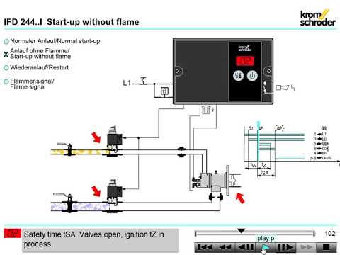
➔ After the safety time tSA(3, 5 or 10 s) has elapsed, the IFD signals a fault. The display indicates a blinking 02.
7. Open the gas shut-off valve.
8. Reset the IFD by pressing the Reset/Information button.
9. Start the program for the burner: apply voltage to terminal 3.
➔ The display indicates 02, the gas valve V1 opens and the burner ignites.
➔ After the safety time tSA(3, 5 or 10 s) has elapsed, the display indicates 04.
➔ The burner is in operation
Assistance in the event of malfunction
Fault Cause Remedy
The display blinks and indicates 01 1. The IFD has detected an incorrect flame signal without the burner having been ignited (extraneous signal)
2. Flame signal through ceramic insulation Increase value of parameter 04 in order to adapt the switch-off threshold of the flame amplifier
Startup – no ignition spark occurs – the display blinks and
indicates 02 1.Gap between ignition electrode and burner head is too great
2. Ignition cable not contacting in the electrode adapter / ignition transformer
3. Ignition cable has short-circuited to ground
4. The ignition cable is too long
5. The ignition transformer is not connected to terminal 5 1. Adjust gap to max. 2 mm
2. Screw the cable on firmly.
3. Check installation, clean the ignition electrode
4. Shorten it to 1 m (max. 5 m)
5. Check the voltage supply to the ignition transformer.
Startup – no gas supply the display blinks and indicates 02 1.The gas valve does not open
2. There is still air in the pipeline, for example after installation work or if the system has not been used
for a long period 1.Check voltage supply to the gas valve
2. “Purge” the pipeline and reset the system several times
Operation – flame burning burner interrupted the display blinks and indicates 04 1.Short-circuit on the ionization electrode as the result of soot, dirt or moisture on the insulator
2. Ionization electrode not correctly positioned at the flame edge
3. Gas/air ratio incorrect 1.Clean Ionization electrode and positioned correctly
#Electrical
#Electronics
#technology
#repairing
#Services
#engineering
#tech
#howto
#testing
#machine
#industry
#maintenance
Reading off the flame signal and the parameters
Press the Reset/Information button for 2 s. The display changes to parameter 01.
Release the Reset/Information button. The display stops at this parameter and indicates the related value.
Press the Reset/Information button again for 1 s. The display changes to the next parameter. All parameters can be recalled one after the other in this way.
➔If the button is pressed only briefly, the display indicates what parameter is currently being displayed.
➔The normal program status is displayed again approx. 60 seconds after the last time the button is pressed.
Parameter list
Code Description
01 Flame signal (0–25 µA).
04 Burner switch-off threshold (2–20 µA).
12 Burner restart:0 = Immediate fault lock-out,1 = Restart.
14 Safety time during operation for gas valve (1; 2s).
22 Burner safety time on start-up (3; 5; 10 s).
81 Last fault.
82 Second to last occurring fault
83 Third to last occurring fault.
84 Fourth to last occurring fault.
.........
90 Tenth to last occurring fault.
🔌𝘽𝙪𝙧𝙣𝙚𝙧 𝙁𝙡𝙖𝙢𝙚 𝙍𝙤𝙙 𝙎𝙞𝙜𝙣𝙖𝙡 𝙈𝙚𝙖𝙨𝙪𝙧𝙞𝙣𝙜 𝙬𝙖𝙮 (𝘿𝙞𝙜𝙞𝙩𝙖𝙡 𝙢𝙪𝙡𝙩𝙞𝙢𝙚𝙩𝙚𝙧 𝙖𝙣𝙙 𝙄𝙁𝘿244 𝙘𝙤𝙣𝙩𝙧𝙤𝙡𝙡𝙚𝙧)
#flamerod #signal #IFD244 #Burner #maxon #electrical #electronics #industry #detection #flame #trending #howto #electricvideo
🛸𝙁𝙡𝙖𝙢𝙚 𝙧𝙤𝙙 𝙨𝙞𝙜𝙣𝙖𝙡 𝙩𝙚𝙨𝙩𝙞𝙣𝙜 𝙗𝙮 𝙙𝙞𝙜𝙞𝙩𝙖𝙡 𝙢𝙪𝙡𝙩𝙞 𝙢𝙚𝙩𝙚𝙧
👨🔧𝙈𝙖𝙭𝙤𝙣 𝘼𝙪𝙩𝙤𝙢𝙖𝙩𝙞𝙘 𝘽𝙪𝙧𝙣𝙚𝙧 𝙊𝙥𝙚𝙧𝙖𝙩𝙞𝙤𝙣
🧰𝙁𝙪𝙣𝙘𝙩𝙞𝙤𝙣 𝙤𝙛 𝙩𝙝𝙚 𝙖𝙪𝙩𝙤𝙢𝙖𝙩𝙞𝙘 𝙗𝙪𝙧𝙣𝙚𝙧 𝙘𝙤𝙣𝙩𝙧𝙤𝙡 𝙪𝙣𝙞𝙩 𝙄𝙁𝘿 244
ℙ𝕝𝕖𝕒𝕤𝕖 🙏 𝕃𝕚𝕜𝕖 👍 𝕊𝕙𝕒𝕣𝕖 🌀 𝕊𝕦𝕓𝕤𝕔𝕣𝕚𝕓𝕖 👆
IFD 244
Gas burner monitoring with an ionization electrode. For grounded systems. With restart after a flame failure.
Commissioning
➔ During operation, the 7-segment display shows the program status:
00 Start-up position
01 Waiting time
02 Safety time on start-up
04 Operation.
1. Close the manual valve!
2. Switch on the system.
3. Apply voltage to terminal 1.
4. Check the electrical installation.
5. Switch on the IFD.
➔ The display indicates 00.
➔ The IFD retains its switch position when the voltage is removed from terminal 1.
6. Start the program for the burner: apply voltage to terminal 3 – the display indicates 0 1.
➔ ϑ signal minimum ON time (terminal 3):
IFD..-3: 8 s
IFD..-5: 10 s
IFD..-10: 15 s
The times must be at least this long, otherwise the automatic burner control unit cannot monitor the burner.
➔ Gas valve V1 opens, the burner ignites and the display indicates 02.
➔ Ignition time tZ:
IFD..-3: 2 s
IFD..-5: 3 s
IFD..-10: 6 s
➔ After the safety time tSA(3, 5 or 10 s) has elapsed, the IFD signals a fault. The display indicates a blinking 02.
7. Open the gas shut-off valve.
8. Reset the IFD by pressing the Reset/Information button.
9. Start the program for the burner: apply voltage to terminal 3.
➔ The display indicates 02, the gas valve V1 opens and the burner ignites.
➔ After the safety time tSA(3, 5 or 10 s) has elapsed, the display indicates 04.
➔ The burner is in operation
Assistance in the event of malfunction
Fault Cause Remedy
The display blinks and indicates 01 1. The IFD has detected an incorrect flame signal without the burner having been ignited (extraneous signal)
2. Flame signal through ceramic insulation Increase value of parameter 04 in order to adapt the switch-off threshold of the flame amplifier
Startup – no ignition spark occurs – the display blinks and
indicates 02 1.Gap between ignition electrode and burner head is too great
2. Ignition cable not contacting in the electrode adapter / ignition transformer
3. Ignition cable has short-circuited to ground
4. The ignition cable is too long
5. The ignition transformer is not connected to terminal 5 1. Adjust gap to max. 2 mm
2. Screw the cable on firmly.
3. Check installation, clean the ignition electrode
4. Shorten it to 1 m (max. 5 m)
5. Check the voltage supply to the ignition transformer.
Startup – no gas supply the display blinks and indicates 02 1.The gas valve does not open
2. There is still air in the pipeline, for example after installation work or if the system has not been used
for a long period 1.Check voltage supply to the gas valve
2. “Purge” the pipeline and reset the system several times
Operation – flame burning burner interrupted the display blinks and indicates 04 1.Short-circuit on the ionization electrode as the result of soot, dirt or moisture on the insulator
2. Ionization electrode not correctly positioned at the flame edge
3. Gas/air ratio incorrect 1.Clean Ionization electrode and positioned correctly
#Electrical
#Electronics
#technology
#repairing
#Services
#engineering
#tech
#howto
#testing
#machine
#industry
#maintenance
Reading off the flame signal and the parameters
Press the Reset/Information button for 2 s. The display changes to parameter 01.
Release the Reset/Information button. The display stops at this parameter and indicates the related value.
Press the Reset/Information button again for 1 s. The display changes to the next parameter. All parameters can be recalled one after the other in this way.
➔If the button is pressed only briefly, the display indicates what parameter is currently being displayed.
➔The normal program status is displayed again approx. 60 seconds after the last time the button is pressed.
Parameter list
Code Description
01 Flame signal (0–25 µA).
04 Burner switch-off threshold (2–20 µA).
12 Burner restart:0 = Immediate fault lock-out,1 = Restart.
14 Safety time during operation for gas valve (1; 2s).
22 Burner safety time on start-up (3; 5; 10 s).
81 Last fault.
82 Second to last occurring fault
83 Third to last occurring fault.
84 Fourth to last occurring fault.
.........
90 Tenth to last occurring fault.
🔌𝘽𝙪𝙧𝙣𝙚𝙧 𝙁𝙡𝙖𝙢𝙚 𝙍𝙤𝙙 𝙎𝙞𝙜𝙣𝙖𝙡 𝙈𝙚𝙖𝙨𝙪𝙧𝙞𝙣𝙜 𝙬𝙖𝙮 (𝘿𝙞𝙜𝙞𝙩𝙖𝙡 𝙢𝙪𝙡𝙩𝙞𝙢𝙚𝙩𝙚𝙧 𝙖𝙣𝙙 𝙄𝙁𝘿244 𝙘𝙤𝙣𝙩𝙧𝙤𝙡𝙡𝙚𝙧)
#flamerod #signal #IFD244 #Burner #maxon #electrical #electronics #industry #detection #flame #trending #howto #electricvideo
🛸𝙁𝙡𝙖𝙢𝙚 𝙧𝙤𝙙 𝙨𝙞𝙜𝙣𝙖𝙡 𝙩𝙚𝙨𝙩𝙞𝙣𝙜 𝙗𝙮 𝙙𝙞𝙜𝙞𝙩𝙖𝙡 𝙢𝙪𝙡𝙩𝙞 𝙢𝙚𝙩𝙚𝙧
👨🔧𝙈𝙖𝙭𝙤𝙣 𝘼𝙪𝙩𝙤𝙢𝙖𝙩𝙞𝙘 𝘽𝙪𝙧𝙣𝙚𝙧 𝙊𝙥𝙚𝙧𝙖𝙩𝙞𝙤𝙣
🧰𝙁𝙪𝙣𝙘𝙩𝙞𝙤𝙣 𝙤𝙛 𝙩𝙝𝙚 𝙖𝙪𝙩𝙤𝙢𝙖𝙩𝙞𝙘 𝙗𝙪𝙧𝙣𝙚𝙧 𝙘𝙤𝙣𝙩𝙧𝙤𝙡 𝙪𝙣𝙞𝙩 𝙄𝙁𝘿 244
 0:02:50
𝐈𝐅𝐃 𝟐𝟒𝟒 𝐊𝐫𝐨𝐦 𝐒𝐜𝐡𝐫𝐨𝐝𝐞𝐫 | 𝐀𝐮𝐭𝐨𝐦𝐚𝐭𝐢𝐜 𝐛𝐮𝐫𝐧𝐞𝐫 𝐜𝐨𝐧𝐭𝐫𝐨𝐥 𝐮𝐧𝐢𝐭 | 𝐂𝐨𝐦𝐦𝐢𝐬𝐬𝐢𝐨𝐧𝐢𝐧𝐠 | 𝐑𝐞𝐚𝐝𝐢𝐧𝐠 𝐨𝐟 𝐭𝐡𝐞 𝐩𝐚𝐫𝐚𝐦𝐞𝐭𝐞𝐫𝐬...
 0:01:55
Автомат керування пальниками Kromschroder IFD 244
 0:02:14
IFD 244 burner controller parameter checking and operation @FlowChart
 0:01:50
Function of the automatic burner control unit IFD 244 | Flow Chart @FlowChart
 0:01:01
𝐈𝐅𝐃𝟐𝟒𝟒 𝐁𝐮𝐫𝐧𝐞𝐫 𝐂𝐨𝐧𝐭𝐫𝐨𝐥 𝐔𝐧𝐢𝐭 𝐓𝐫𝐨𝐮𝐛𝐥𝐞𝐬𝐡𝐨𝐨𝐭𝐢𝐧𝐠| 𝐃𝐢𝐬𝐩𝐥𝐚𝐲 𝐢𝐬 𝐧𝐨𝐭 𝐥𝐢𝐭 𝐚𝐧𝐝 𝐧𝐨𝐭𝐡𝐢𝐧𝐠 𝐢𝐬 𝐢𝐧𝐝𝐢𝐜𝐚𝐭𝐞d@FlowChart...
 0:00:16
Kromschroder IFD244 Parameter Scanning @FlowChart
 0:00:16
Kromschroder IFD244 CKT | Temperature sensor #IFD244 #electrical #electronics #kromscroder
 0:00:43
how to reset Kromschroder / honeyeell burner controller fire fault IFD244
 0:00:31
kromschroder ifd 258 series with p300bc100 operating flame rod mode
 0:00:10
krom Schroder IFW 15 testing #flamerelay #burner
 0:00:37
kromschroder UVS10 D1G1
 0:00:42
Kromschroder uvs 10d0g1
 0:04:25
Kromschröder IFD 258 overview
 0:04:44
Kromschroder FCU 500
 0:00:39
krom Schroder relays #flamengo #burner
 0:00:52
KROM/SCHRODER IC 20-30W3E 88300076
 0:02:40
Автомати керування пальниками Kromschroeder IFD 258
 0:01:57
Сервоприводы Kromschroder IC20, IC40
 0:01:01
KROMSCHRODER IFD 258-5/1W (IN STOCK) Flame detector 220 V - Rilevatore di fiamma
 0:00:29
Kromschroder IFD258-5/1W
 0:00:20
Gas Solenoid Krom Schroder Dn20 Max150mbr (ID2648)
 0:00:47
Автомат управления горелкой IFD 244-5 1WI 84621046
 0:00:11
Burner kromschroeder
 0:00:52
KROM/SCHRODER IC 20-30W3E 88300076
Комментарии