filmov
tv
In the circuit diagram given below, three resistors R1, R2, and R3 of 5 Ω, 10 Ω, and 30 Ω respectiv

Показать описание
#2_pi_classes #schandsolutions #ncertsolutions #electricity #ncertclass10science
#Inthecircuitdiagramgivenbelowthreeresistors
_____________________________________________________________________
In the circuit diagram given below, three resistors R1, R2, and R3 of 5 Ω, 10 Ω, and 30 Ω respectively are connected as shown:
Calculate:
a) current through each resistor
b) total current in the circuit
c) total resistance in the circuit
______________________________________________________________________
Chemistry link:
--------------------------
_____________________________________________________________________
Physics link-
---------------------
________________________________________________________________
Maths link-
--------------------
__________________________________________________________________________________________
Thank You !
By - Vineet Pandey
 0:03:55
In the circuit diagram given alongside, find: (i) total resistance of the circuit, (ii) total curren
 0:04:49
Drawing an Open Circuit Diagram
 0:01:30
How to Find the Boolean Expression from a Circuit Diagram
 0:03:32
in the given following circuit diagram if R1=R2=R3=R4=R5=3 Ω find the equivalent
 0:03:48
Circuit diagram - Simple circuits | Electricity and Circuits | Don't Memorise
 0:04:56
Series and Parallel Circuits | Electricity | Physics | FuseSchool
 0:02:15
Circuit diagram|electric circuit diagram|how to draw circuit diagram
 0:02:23
The circuit diagram shown here corresponds to the logic gate
 0:00:59
check a Bluetooth Amplifier project #shortvideo
 0:34:18
How To Solve Any Resistors In Series and Parallel Combination Circuit Problems in Physics
 0:02:36
Electric Circuit Diagram
 0:02:39
HOW TO DRAW A CIRCUIT DIAGRAM USING LOGIC GATES? | PROPOSITIONAL LOGIC (PART 4) | ISC CLASS 11
 0:07:19
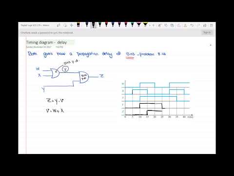
Timing diagram of the circuit with propagation delay
 0:02:45
In the given circuit diagram, a wire is joining points B and D. The current in this wire is-
 0:11:53
Natural Science Circuit Diagram Application Grade 9
 0:11:27
How To Calculate The Current In a Parallel Circuit Using Ohm's Law
 0:03:10
To draw the diagram of given circuit. and correct the circuit diagram. Activity 3 class 12 CBSE
 0:01:37
Circuit Diagram | Simple Circuits | Electricity and Circuits | YoKIdz Channel | YoKIdz Drawing
 0:15:23
Equivalent Resistance of Complex Circuits - Resistors In Series and Parallel Combinations
 0:06:22
Find Boolean Equation and Truth Table from Logic Diagram
 0:30:33
AC Circuits - Impedance & Resonant Frequency
 0:13:02
Wheatstone bridge & its logic | Electric current | Physics | Khan Academy
 0:09:33
Problem Finding Complete Sequence Diagram of Counter
 0:35:54
How to Draw a State Transition Diagram? Analysis of Clocked Sequential Circuits
Комментарии