filmov
tv
Cisco RSTP Configuration | CCNA 200-301 | IPCisco.com

Показать описание
.
.
-----------------------------------------------------------
Useful Pages:
---------------------------------------
. #ccna #cisconetworking #spanningtree #packettracer #stpconfiguration .
STP Overview
-----------------------
In Layer 2 domain, redundancy is an important case. To provide redundant links, multiple connections are done between switches. But this redundancy mechanism can cause an undesirable situation that is called "L2 Loop". To provide L2 redundancy and to avoid L2 loops, Spanning Tree Protocol (STP) has been developed.
During the development period, various versions of STP has been introduced. Different standards has been created beside Cisco specific versions. These STP versions are :
• STP (Spanning Tree Protocol) – 802.1D
• RSTP (Rapid Spanning Tree Protocol) – 802.1W
• PVST+ (Per VLAN Spanning Tree Plus) – Cisco Proprietary
• Rapid PVST+ (Rapid Per VLAN Spanning Tree Plus) – Cisco Proprietary
• MST (Multiple Spanning Tree) – 802.1s
In this article, mainly we will focus on STP (802.1D).
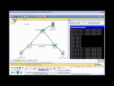
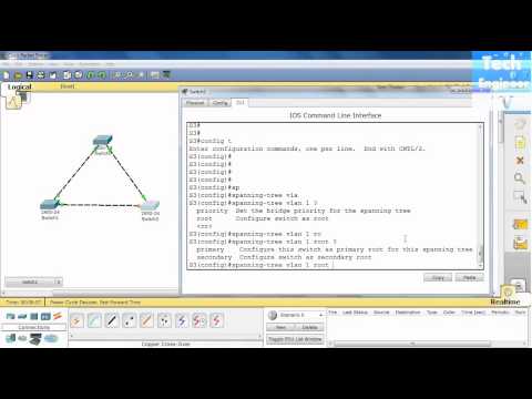
Packet Tracer STP Configuration
In this post, instead of detaily talk about STP (Spanning Tree Protocol), we will focus on a basic Switching Loop topology and how STP mechanism helps to avoid this Switching Loop.
Switching Loop is an unwanted problem in a network. Then, what is Switching Loop? Switching Loop is the situation, in which there are two layer 2 path between two layer 2 endpoint(switch, brigde). Switches creates broadcast storms from every port and switch rebroadcast again and again. Because of teh fact that there is no TTL(time to live) mechanism on layer 2, this continues forever.
To avoid this unwanted Switching Loops, there are some mechanisms. One of the most common name of this mechanisms is STP(Spanning Tree Protocol).
Acording to this protocol, in the switching topology, a Root Bridge is selected. And then the connected port of the switches are classified. The port classification and their meaning are like below:
– Root Port : The port to the Root Bridge
– Designated Port : The other port thatis not Root Port
– Non Designated (Blocked) Port : In a segment, other port than the Designated Port
The selection process is done orderly. First Root Bridge is selected, secondly Root Ports on all the switches, then Designated Ports are selected, and lastly the remainning ports become Non-Designated Port, meaning Blocking Port.
STP Configuration in Cisco Packet Tracer,
Cisco Packet Tracer CCNA Labs Adventures!
Конфигурация STP в Packet Tracer,
Configuración de STP en Packet Tracer,
Configuração STP no Packet Tracer,
Configurazione STP su Packet Tracer,
Configuration STP sur Packet Tracer
Packet Tracer STP Configuration,
تكوين STP على حزمة التتبع
पैकेट ट्रेसर पर STP कॉन्फ़िगरेशन
.
-----------------------------------------------------------
Useful Pages:
---------------------------------------
. #ccna #cisconetworking #spanningtree #packettracer #stpconfiguration .
STP Overview
-----------------------
In Layer 2 domain, redundancy is an important case. To provide redundant links, multiple connections are done between switches. But this redundancy mechanism can cause an undesirable situation that is called "L2 Loop". To provide L2 redundancy and to avoid L2 loops, Spanning Tree Protocol (STP) has been developed.
During the development period, various versions of STP has been introduced. Different standards has been created beside Cisco specific versions. These STP versions are :
• STP (Spanning Tree Protocol) – 802.1D
• RSTP (Rapid Spanning Tree Protocol) – 802.1W
• PVST+ (Per VLAN Spanning Tree Plus) – Cisco Proprietary
• Rapid PVST+ (Rapid Per VLAN Spanning Tree Plus) – Cisco Proprietary
• MST (Multiple Spanning Tree) – 802.1s
In this article, mainly we will focus on STP (802.1D).
Packet Tracer STP Configuration
In this post, instead of detaily talk about STP (Spanning Tree Protocol), we will focus on a basic Switching Loop topology and how STP mechanism helps to avoid this Switching Loop.
Switching Loop is an unwanted problem in a network. Then, what is Switching Loop? Switching Loop is the situation, in which there are two layer 2 path between two layer 2 endpoint(switch, brigde). Switches creates broadcast storms from every port and switch rebroadcast again and again. Because of teh fact that there is no TTL(time to live) mechanism on layer 2, this continues forever.
To avoid this unwanted Switching Loops, there are some mechanisms. One of the most common name of this mechanisms is STP(Spanning Tree Protocol).
Acording to this protocol, in the switching topology, a Root Bridge is selected. And then the connected port of the switches are classified. The port classification and their meaning are like below:
– Root Port : The port to the Root Bridge
– Designated Port : The other port thatis not Root Port
– Non Designated (Blocked) Port : In a segment, other port than the Designated Port
The selection process is done orderly. First Root Bridge is selected, secondly Root Ports on all the switches, then Designated Ports are selected, and lastly the remainning ports become Non-Designated Port, meaning Blocking Port.
STP Configuration in Cisco Packet Tracer,
Cisco Packet Tracer CCNA Labs Adventures!
Конфигурация STP в Packet Tracer,
Configuración de STP en Packet Tracer,
Configuração STP no Packet Tracer,
Configurazione STP su Packet Tracer,
Configuration STP sur Packet Tracer
Packet Tracer STP Configuration,
تكوين STP على حزمة التتبع
पैकेट ट्रेसर पर STP कॉन्फ़िगरेशन
 0:43:01
 0:08:47
 0:04:51
 0:03:46
 0:01:00
 0:12:31
 0:06:56
 0:03:49
 0:12:44
 0:12:33
 0:01:00
 0:05:05
 0:25:27
 0:10:00
 0:01:00
 0:24:41
 0:12:15
 0:15:24
 0:10:27
 0:08:12
 0:00:24
 0:14:32
 0:02:12
 1:04:52