filmov
tv
How Serial verse Parallel Data Transfer Works (Intro to Digital Logic Part 2)
Показать описание
In this video we will be going over how a computer transfers data in serial transfer and parallel transfer
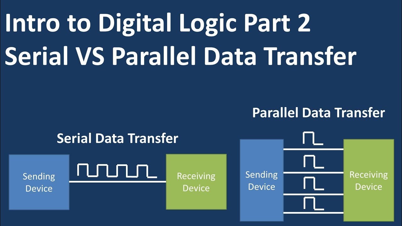
We will start off with a serial data transfer.
In serial data transfer there is a single line that is used for data transfer which connects the sending device to the receiving device. As depicted on the slide.
We will need to know some terminology to determine how the data will be transferred.
We have the clock which a periodic square waveform used for timing and synchronizing data transfer
We binary number which is a 2 state number system which consists of logic 1 on state or logic 0 off state
And finally a bit which is 1 digit of a binary number so a 1 or 0 As pictured and represented as a letter A these bits form a square waveform that will be sent on the line connecting the sending and receiving device
There is a clock that is continuously running and each period is the time required to transfer 1 bit of data. This is also referred to as bit time
In this example we will assume the data is transferred every time the rising edge of the clock square wave happens.
We can see from the diagram that for every cycle of the clock 1 bit is transferred during that duration of the clock cycle
So at the rising edge of the clock wave form at t zero a 1 is transferred
at t one a zero is transferred
and at t two a zero is transferred and so on and so forth
Now in parallel data transfer there is a sending device that is connected to the receiving device with multiple lines where data can be transferred. In this case there are 3 lines connecting the sending device to the receiving device.
When the clock cycle rising edge happens each line puts out a 1 bit 0 or 1 signal to the receiving device.
So in this case at t zero line C has a 1, line B has a 0 ,and line A has a 1. At t1 line c has a 1 line b has a 1 and line A has a zero
So now lets compare time when sending 4 bits of information in series verse parallel.
In series there is 1 path which can transferred 1 bit per clock cycle
So the time to transfer 4 bits will be 4 clock cycles
In this parallel circuit on the other hand we have 4 paths which each path can transfer 1 bit per clock cycle
So the time to transfer 4 bits is one clock cycle
It is useful to note that at faster clock cycle the more data will be transferred. PC enthusiasts will increase the clock cycle to increase the speed of their machine this is known as overclocking.
The major advantage of series is that only one line is needed to transfer data. This can results in a lower cost due to not having redundant components compared to parallel.
The major advantage of parallel data transfer is that you can transfer data faster assuming the same clock speed.
Disclaimer
These videos are intended for educational purposes only (students trying to pass a class) If you design or build something based off of these videos you do so at your own risk. I am not a professional engineer and this should not be considered engineering advice. Consult an engineer if you feel you may put someone at risk.
 0:03:26
How Serial verse Parallel Data Transfer Works (Intro to Digital Logic Part 2)
 0:05:59
Serial and Parallel Data Transmission
 0:01:06
Serial vs Parallel Data Transmission (GCSE Computer Science)
 0:08:09
Data Transmission - Serial Vs Parallel Data Transmission
 0:12:16
The PARALLELOSLAM - Converting Serial to Parallel For Your Devious Purposes
 0:12:33
Serial & Parallel Data Transmission
 0:09:14
A Brief Intro to Digital Logic - Serial vs Parallel Digital Data Communication (DA04)
 0:09:23
Parallel to Serial Data Conversion via AT89S52 Microcontroller
 0:01:57
What's the difference between parallel and serial data transmission?
 0:05:24
L 61: SERIAL AND PARALLEL DATA TRANSMISSION
 0:10:15
Parallel and Serial Transmission of Digital Data
 0:00:58
Serial to Parallel and parallel to serial
 0:28:55
Serial Data Transmission - Simply Put
 0:01:52
Molex - Product Spotlight - Camera Sockets for Serial and Parallel Data Applications v2
 0:39:45
DLD | Digital Waveform | Serial & Parallel Data Transfer |
 0:25:03
Building the CPU: Datapath - Parallel and Serial Buses
 0:00:19
Define serial to parallel conversion | Microprocessor and Microcontroller Interview Questions
 0:19:58
eapbg #14 LCDs and Introduction to Parallel Bus
 0:04:45
Unix & Linux: Why is serial data transmission faster than parallel? (5 Solutions!!)
 0:05:46
Parallel Bus Comm
 0:20:10
SERIAL VS. PARALLEL BUSSES FOR PROCESSING & FX
 0:11:05
Lesson 4 serial to parallel Part 1
 0:06:34
What's the Difference Between Parallel and Serial transmission mode?
 0:00:57
Parallel to Serial using Logic Blocks
Комментарии