filmov
tv
Arduino Tutorial LED Bar Graph #arduinoproject

Показать описание
In this LIVE session we will be showing you how to connect an LED Bar Graph to your Arduino.
This was filmed live, skip to 2m if you want to get straight into the action.
We will use a variable resistor to control the segments illuminated on the LED Bar Graph. This tutorial will show you the parts needed, connection and code. #arduinounoprojects #simplearduinoprojects
Parts Used
=========
1x Arduino Uno R3 ( freenove clone )
14x Jumper Wires
1x Potentiometer
14x 220R Resistor
1x Breadboard
1x 10 Segment LED Bar Graph Display
Skip straight to the section that interests you
====================================
00:00 Introduction
02:00 Build the Schematic in Labcenter Proteus VSM
07:12 Write the sketch in Arduino IDE
16:53 Run the code in Proteus VSM Arduino Simulator
17:54 Build the real Electronics
25:05 Program the sketch into the Arduino Uno R3
25:18 Test the sketch on the electronics hardware
26:10 Outro
All of the parts used came from one kit - Freenove Arduino RFID Kit purchased from Amazon ( direct link - this is NOT an affiliate link )
 0:26:46
Arduino Tutorial LED Bar Graph #arduinoproject
 0:07:53
{734} LED Bar Graph Using map Function Arduino Uno Code
 0:15:13
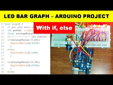
{721} LED Bar Graph Arduino Uno Code Using if else || Arduino Project
 0:11:18
Arduino Prototyping Outputs #74: LED Bar Graphs
 0:01:29
How to use LED BAR GRAPH with Arduino
 0:10:55
CONTROL LED DOT MATRIX WITH ARDUINO | Led bar graph
 0:00:16
LED Bar Graph with Arduino
 0:20:05
Designing LED Bar graph with Arduino
 0:25:14
Pico W Episode 31: LED Displays Bar Graph with a Shift Register 74HC595 Part 4
 0:24:21
Arduino Temperature Sensor LED Bar Graph
 0:10:49
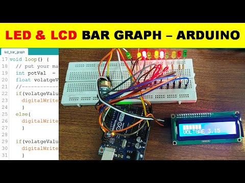
{722} LCD & LED Bar Graph Arduino Uno Code Using if else
 0:07:19
Arduino Basics: Mastering the 10-Segment LED Bar Graph In Your Project
 0:03:53
how to make LED Bar Graph with arduino
 0:12:16
Arduino Led Bar Graph
 0:02:29
How to do LED Bar Graph using Arduino Uno with arduino ide software .
 0:18:27
TinkerCad Arduinoweb Editor Project 3.1 LED bar graph Display
 0:01:30
Arduino Project Handbook - LED Bar Graph
 0:15:59
{443} LED Bar Graph Arduino Uno Code Using if else || Arduino Project
 0:00:35
Arduino LED Bar Graph Driven by a 4017 Counter and Potentiometer
 0:05:16
#Arduino project|Led Bar Graph
 0:01:04
Arduino: Potentiometer LED Bar Graph Code, Sketch & Wiring Diagram Schematic
 0:05:29
Arduino Project - Moving Dot LED Display
 0:00:53
Arduino - Led bar graph controlled with potentiometer
 0:13:31
#3 | Led Bar Graph💡 | Basic Arduino Projects for Beginners | Top Arduino Projects
Комментарии