filmov
tv
DC Model Train Layout Block Wiring And Analog Locomotive Contro

Показать описание
Share, Like, Comment Or Subscribe.
This selection DC Model Train Layout Block Wiring And Analog Locomotive Control is from our library of diorama and scale model scenery tutorials. The library is one of many others we have that contain videos covering all aspects of model railroading and making dioramas.
For Barbecue, Camping, RV, Clubs
A DC layout with block wiring can also be used to run DCC enabled locomotives.
And you can use DCC on a DC layout with block wiring. You do that by disconnecting your dc power, and switching all blocks to a single cab position. With all blocks thus connected, you can use your DCC Control Station as you normally would.
 0:06:26
DC Model Train Layout Block Wiring And Analog Locomotive Contro
 0:10:36
019 Laying Track, Installing Yard, and DC Wiring with Terminal Blocks
 0:14:38
How to Install an Electric Block on your Layout!
 0:35:07
LAYOUT WIRING for DC and DCC and all gauges at Chadwick Model Railway | 175.
 0:17:25
DC, DCC and Block Detection at Chadwick Model Railway | 78.
 0:40:20
Wiring My Model Railroad For DC And DCC Power - Bus Line And Feeders
 0:18:51
Block signalling SS2A DC shuttle
 0:08:45
Why Blocks: The case for electrically dividing a layout into parts...
 0:05:37
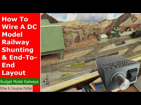
How To Wire A DC Model Railway / Railroad Shunting & End-To-End Layout Easily With Only 2 Wires!
 0:11:54
Model Railway Wiring Update - Switching Isolated Sidings
 0:10:05
Basic Wiring For Your DC Layout - Model Railroading For Beginners Ep 20
 0:07:12
How To Use The Block Signalling Model Railway / Railroad Shuttle Unit - Tutorial Tuesday Episode 28
 0:06:39
Ho DC layout isolation wiring
 0:11:24
How To Wire Your Model Train Layout Part 2 - Basic Wiring Techniques - Block Control Wiring
 0:24:46
Model Railroading For Beginners - DC Wiring 101 - Ep 10
 0:08:03
Wiring A Model Railway For Beginners - Model Railway Basics: Episode 3
 0:17:41
Terminal Blocks for model railway wiring at Chadwick Model Railway | 85.
 0:14:54
Installing a Block using Atlas Selector #215
 0:33:00
How to and why to use terminal blocks on your model train layout. Also different types to use
 0:05:06
DCC Train Control Systems For Model Railroad Beginners Explained 😄
 0:11:24
Introduction to DC Block Wiring - Electricity for Model Railroads
 0:08:55
How to use Block terminals with your O gauge layout
 0:21:41
Have the Best of Both Worlds!! Simplest Explanation EVER on Wiring Questions.
 0:37:18
An Intro to Block Detection at Chadwick Model Railway | 137.
Комментарии