filmov
tv
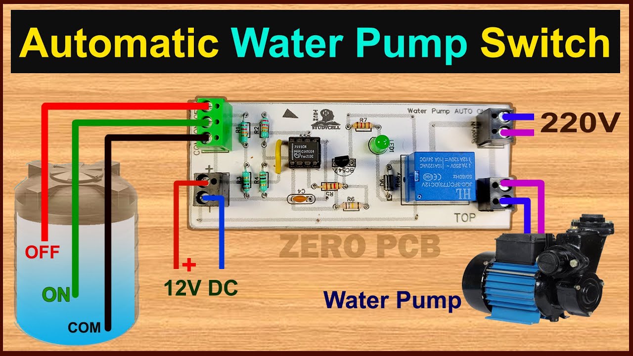
How to make Water Pump Automatic Switch ON-OFF Circuit | Water Level Controller with 555
Показать описание
In this project, I have shown how to make water pump automatic switch ON-OFF circuit to control the water level automatically. I have used the 555 timer IC for this DIY water pump auto cut switch circuit.
With this simple 555 timer circuit, we can stop the water overflow from the water tank. And the pump will automatically start if the water level becomes low. So we don't need to start and stop the pump manually.
I have published a new water pump controller circuit with more features. Please click the following link to watch the tutorial.
New water pump controller using Arduino
Download the PCB Layout for Automatic ON\OFF water pump switch from the following article
Required components for the water pump automatic control circuit
1. 555Timer IC (1no)
2. BC547 NPN Transistor (1no)
3. 1k 0.25watt Resistors (R5, R7) (2no)
4. 22k 0.25watt Resistors (R1, R2) (2no)
5. 180k 0.25watt Resistor (R6) (1no)
6. 1M 0.25watt Resistors (R3, R4) (2no)
7. 100nF (104) Capacitor (C4) (1no)
8. 1N4007 Diode (D6) (1no)
9. LED 1.5V (1no)
10. 12V SPDT Relay (1no)
11. Connectors & IC base (4pin)
12. Zero PCB
Here, I have used a 5V pump to show the operation, but you can also use any single-phase pump. Please select the relay as per the voltage and current rating of the pump.
After watching the video, you can easily design this automatic water tank level controller motor driver circuit for your home.
If you face any issue please let me know in the comment section.
#waterpumpautocutswitch #waterpumpautoonoff
------------------------------------------------------
Thanks For Watching...
✅ SUBSCRIBE ✅LIKE ✅SHARE ✅ COMMENTS
-------------------------------------------------------
Other useful videos:
LM317 variable DC Power Supply with circuit diagram
How to calculate resistor value for LEDs in a circuit for 9V and 12V
 0:04:38
Make a HOMEMADE WATER PUMP with simple materials!WATER PUMP!
 0:06:05
How to make the smallest water pump at home - diy water pump using mini dc motor
 0:02:18
How to make Water Pump with dc motor | Global fun
 0:03:26
How to Make a Water Pump from Motor at Home | Awesome Ideas
 0:02:41
How to make high speedy mini water pump at home
 0:13:27
How to make Powerful Water Pump 12volt With 775 Motor
 0:05:53
How To Make a Water Pump From DC Motor at Home | DC Motor Ideas
 0:04:20
How to make water pump at home | Mini water pump | DC motor water pump
 0:00:25
How to Make a Water Pump with 4 Stroke Gasoline Engine #stirlingkit #engine
 0:00:59
Diy how to make mini water pump science project #shorts
 0:03:19
How to make Water Pump From Dc Motor at Home
 0:07:37
How to make Powerful Water Pump - Homemade High Pressure Pump
 0:00:56
How to Make Diy Water Pump #diy
 0:23:21
DIY Powerful Water pump - How to Make a Water Pump at Home
 0:00:11
Best Hand Water Pump Ever!
 0:16:52
How To Make A Simple Water Pump Using Drill Machine | Diy Powerful Water Pump | DIY
 0:00:57
How to Make a Water Pump from Motor at Home | Awesome Ideas
 0:05:45
How to make a giant water pump 1 no 2
 0:10:53
How To Make Water Pump 12V At Home,Water Pump From PVC Pipe/V19 #waterpump#diywaterpump
 0:00:45
How to make water pump science project
 0:01:00
Trick Free electricity | I turn PVC pipe into a water pump at home free no need electricity power
 0:00:16
#short | HiFi Mini DC water pump | powerful water pump | DC submersible | water | short video
 0:08:12
How To Make Mini Water Pump At Home With DC Moter Science Project #schoolproject
 0:16:36
How to make Powerful Water Pump Using Drill
Комментарии