filmov
tv
Ask Mark - Parallel Audio Output Tubes Explained

Показать описание
BG283 - We get the question a lot around "can I simply parallel output tubes to increase output power" and what all is involved.
 0:20:53
Ask Mark - Parallel Audio Output Tubes Explained
 0:07:04
How To Set Up An Amplifier [Bridge vs Parallel vs Stereo]
 0:21:32
Ad-Lib Sound Card for the Parallel Port
 0:02:52
how monoblock tube amplifiers are made #4 ; 300B parallel SE GX-2300A 220V version
 0:20:52
Audio 101: What to listen for with Parallel Compression
 0:22:21
He's Been Locked In This Machine For 70 Years - Paul Alexander
 0:11:57
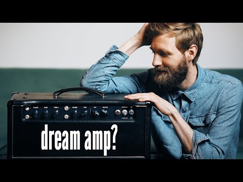
THE BEST SOUNDING AMP I'VE EVER PLAYED // Will it hold up against digital modellers?
 0:06:12
Robert De Niro Impressed By Tom Hiddleston's Robert De Niro Impression - The Graham Norton Show
 0:03:01
Omar Takes The Stand | The Wire | HBO
 0:09:57
Upgrades: WAD 300B Parallel Single-Ended Monobloc amplifier, Final Assembly
 0:05:31
DIY Parallel Single Ended Amplifier Tube @metixfunix5534
 0:14:45
Parallel Filters, Pro Level: Flip It And Reverse It
 0:04:28
What It’s Like Being Married to Neil deGrasse Tyson - Key & Peele
 0:14:23
ProtoDac Amazing HIFI Audio DAC HAT using eight parallel vintage Philips TDA1387 chips.
 0:03:08
DIY Parallel Single Ended Tube Amplifier @metixfunix5534
 0:04:58
You Are Two
 0:36:50
The BEST Parallel Effects Blender! GFI System Duophony | Secret Weapons Demo & Review
 0:02:03
EIMAC 8165/4-65A DIY Integrated Amplifier-Parallel single end / Sigma fp
 0:07:15
AudioNote P2SE Clone - 6L6/5881 Parallel Single Ended Stereo Vacuum Tube Amplifier
 0:14:16
Body Language Expert Explains How to Show Confidence | WIRED
 0:02:01
Pcl84 single ended parallel triode mode
 0:58:15
Jim Grant's Exclusive Reaction To Fed Interest Rate Decision: A 2WAY Conversation
 0:03:36
pre-order 300B parallel SE tube amplifier model F-3A build #2 ; fluxion audio
 0:09:22
Rock Skip Robot- The Science of Perfect Rock Skipping
Комментарии