filmov
tv
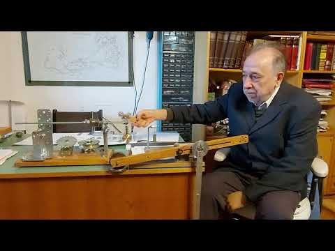
Two Stage Mechanical Oscillator Part III - (Measurements)

Показать описание
Here are the measurements for the Two-Stage Mechanical Oscillator. It was a bit difficult trying to find a good instrument to try to measure with. I finally found these "Belt Tension Gauges", they worked like a charm.
More scientific accuracy is out of my realm and would require a laboratory team or something. But I think these make the point very well.
I would like to say this but can't because there are more accurate measurement methods out there, but I am confident there is more energy coming out of the thing than what is going in. You can look at it and it does indeed appear to be just that.
The only thing I didn't do was measure distance, but just by looking at it, it appears that the input and output distances are very near the same and does not have a very big difference between the two, maybe around an inch or two.
So, force times distance equals work. The force is the pounds in this case and then the distance can be gauged just by looking at it. If a curved tape measure was used then it would probably be exactly the same as the estimated and observed distance.
Have a great one and thanks for watching. Please LIKE, SHARE, COMMENT and SUBSCRIBE.
╔═╦╗╔╦╗╔═╦═╦╦╦╦╗╔═╗
║╚╣║║║╚╣╚╣╔╣╔╣║╚╣═╣
╠╗║╚╝║║╠╗║╚╣║║║║║═╣
╚═╩══╩═╩═╩═╩╝╚╩═╩═╝
 0:12:17
Two Stage Mechanical Oscillator Part I
 0:03:46
How to Make a Two-Stage Oscillator More Efficient
 0:11:35
Two Stage Mechanical Oscillator Part II - (Explanation)
 0:01:20
Milkovic two stage oscillator forever
 0:00:21
Veljko Milkovic - two stage mechanical oscillator - Pendulum - 3DSMAX Reactor Simulation
 0:37:14
Veljko Milkovic - 2 Stage Mechanical Oscillator
 0:00:49
#3 - Veljko Milkovic 's Two-Stage Oscillator Replica Test with Longer Pendulum's Neck
 0:00:41
Electric Generator with Magnets Driven by a Two-Stage Oscillator
 0:00:40
Two stage mechanical oscillator replication, posibly overunity
 0:02:54
TWO STAGE MECHANICAL OSCILLATOR
 0:11:06
Two Stage Electromagnetic Oscillator
 0:01:47
#8 Veljko Milkovic 's Two Stage Oscillator Experiment With a Spring
 0:04:30
New Fast and Improved Two-Stage Oscillator
 0:42:04
Veljko Milkovic 2 Stage Mechanical Oscillator
 0:00:22
#5 Veljko Milkovic 's Two-Stage Oscillator with two freewheels (high losses)
 0:13:22
2. Two Stage Oscillator -escapement idea
 0:01:20
Milkovic two stage oscillator forever 720p
 0:11:24
Final Update of Two Stage Mechanical Oscillator
Two Stage Mechanical Oscillator Part III - (Measurements)
 0:03:49
Curie Effect Mechanical Oscillator
 0:00:29
#2 - Veljko Milkovic 's Two-Stage Oscillator Test - Work In Progress 02 ( Pendulum added)
 0:01:20
Veljko Milkovic - Two Stage Mechanical Oscillator - 3D stereoscopic simulation
 0:04:55
Super 2 Stage Oscillator
 0:02:06
What to do with a double oscilator?
Комментарии