filmov
tv
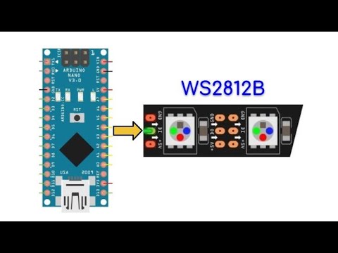
Creating Arduino Library for WS2812B LED Strip

Показать описание
Link to circuit diagram:
Link to my GitHub repository to access WS2812B library:
Link to my tutorial on programming WS2812B using assembly:
Content:
0:00 Introduction
0:35 Sending Bytes to WS2812B
2:20 Programming WS2812B using C++ and assembly
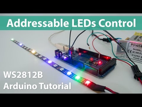
7:38 Demonstrations
8:18 Creating Library: Header & Source Files
10:31 Library Example Sketch: Displaying Patterns on LED Strip
11:26 Demonstration
11:39 Future Project: Update Library to Include More Functions
Link to my GitHub repository to access WS2812B library:
Link to my tutorial on programming WS2812B using assembly:
Content:
0:00 Introduction
0:35 Sending Bytes to WS2812B
2:20 Programming WS2812B using C++ and assembly
7:38 Demonstrations
8:18 Creating Library: Header & Source Files
10:31 Library Example Sketch: Displaying Patterns on LED Strip
11:26 Demonstration
11:39 Future Project: Update Library to Include More Functions
 0:11:52
Creating Arduino Library for WS2812B LED Strip
 0:24:32
HOW TO USE WS2812B NEOPIXELS WITH FASTLED ON ARDUINO
 0:00:33
Pixel Dust on RGB Matrix displays
 0:26:39
How To Program WS2812 LEDs with FastLED and an Arduino
 0:24:45
04-FastLED with Arduino Tutorial Introduction - How to Code for RGB LED Strips (WS2812B)
 0:09:31
How To Control WS2812B Individually Addressable LEDs using Arduino
 0:21:38
The BEST FastLED Tutorial | WS2812b LED Strip Arduino Nano
 0:01:00
Shooting Star Animation for Individually Addressable LEDs (Arduino, WS2812B, FastLED Library)
 0:17:01
How to use Excel to Animate LEDs! Arduino + WS2812 LEDs
 0:05:52
How to use WS2812B RGB LEDs with Arduino
 0:11:51
How to use WS2812 8x8 LED matrix with Arduino and FastLED library
 0:21:22
Ultimate Guide to Programming LED Strips with Arduino | Wiring, Powering & Code with FastLED
 0:01:00
Drive WS2811 Pixel LEDs with Arduino || FastLED Arduino library || RBG LEDs shorts tutorial
 0:08:59
Beginner's Guide to Using LED Strips with Arduino
 0:09:26
Getting Started with RGB NeoPixels| WS2812B
 0:07:24
How to control RGB WS2812B LED 32x8 matrix with an Arduino - Tutorial
 0:01:00
Fire Animation for Individually Addressable LEDs (Arduino, WS2812B, FastLED Library)
 0:02:08
R2D2 WS2812b LED strips - Arduino animations with FAST LED Library
 0:06:06
Modern turn signal lights v4.0 for bikes - Arduino, FastLED and WS2812B
 0:00:47
Create NeoPixel Led Ws2812b Own Library Arduino Uno
 0:10:02
Cheap DIY Arduino Ambilight 2.0 (Revisited) RGB WS2812b LED Full Build & How-To
 0:01:03
WS2812 WS2811 LED Video Arduino LEDStrip effects
 0:02:40
10 Amazing Lighting Effects using Neo Pixel RGB LED's | Part 2 | Using FastLED Library | #NS_Id...
 0:18:35
06-Comet Effect - LED Strip Arduino Tutorial - FastLED Effects - on RGB LED WS2812B and Neopixels
Комментарии