filmov
tv
How to get BCD from Binary with verilog and the Double Dabble algorithm!

Показать описание
**NOTE: the final Verilog script in this video is intended for 4 digit conversion where the initial example is for 3 digit conversion.**
In this video we go through the algorithm to create BCD (Binary Coded Decimal) from Binary with the double dabble method. We then show a verilog example of how to code the Double Dabble algorithm! BCD is a very important number coding in order to drive things like 7 segment LED displays and more. This code will eventually be uploaded to an FPGA board to drive a set of 7 segment displays. The code can be downloaded from my GitHub link below. Please keep an eye out in the description for the upcoming videos that tie into this project! Have a great day and don't forget to #LoveWell!!
GitHub Code:
Binary to BCD Simulation video:
BCD to 7 segment decode:
 0:05:38
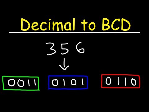
Decimal to BCD
 0:08:55
How to get BCD from Binary with verilog and the Double Dabble algorithm!
 0:13:39
BCD Codes (Binary Coded Decimal Codes) Explained
 0:06:59
#8 Simple Demo of Binary Coded Decimal (BCD) for Real Time Clocks (such as the DS3231 and DS1307)
 0:11:28
BCD Addition
 0:00:16
Binary to Decimal conversion in scientific calculator
 0:11:00
How To Convert Gray Code to Binary and Binary to Gray Code
 0:29:49
Binary to BCD | Logical Redstone #10
 0:00:36
BCD to binary conversion
 0:02:49
How to get BCD on SimpleSwap without sign-up?
 0:00:13
decimal to binary conversion #shorts #binary#trending #viral
 0:00:11
Hexadecimal to decimal conversion in scientific calculator
 0:00:27
How to inflate your bcd at the surface!
 0:00:25
How To:Measure BRA Size #shorts_video #fashion #follow #bhfyp
 0:00:57
The Secret to Perfect Buoyancy While Scuba Diving
 0:00:14
decimal to binary conversion in Casio fx-991ES plus
 0:07:38
Lec-8: BCD, Excess-3 Code & Conversion with example
 0:06:04
How to Fix Windows 11 Won't Boot BCD Error Code 0xc0000098
 0:02:38
Scuba Diving Skills: How to Inflate and Deflate your BCD Using the LPI | Scuba Equipment 101
 0:04:04
How To Make Sure Your BCD Fits
 0:08:16
ASCII Code and Binary
 0:02:12
Scuba Diving: How to Assemble Equipment
 0:01:01
Threading a BCD cam band is easy. See how it’s done #dive #scubadiving #divetips #bcd #shorts
 0:00:31
Binary to Decimal Conversion
Комментарии