filmov
tv
GPIO Output Configuration | Open Drain configuration | Push Pull configuration
Показать описание
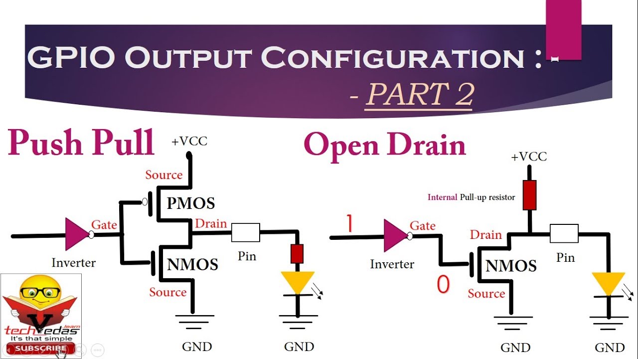
Fundamentals29 GPIO Output Configuration or Open Drain configuration or Push-Pull configuration
Friends welcome to this video series on Embedded System. GPIO which stands for general purpose input output is one of the first things to play with while learning Embedded System programming.
So in this video, let's continue our discussion on this topic and try to understand what is the need of Pullup and pull down registers while making use of GPIOand some of the most commonly used GPIO output configurations like Push pull and Open Drain.
#TechVedasLearn
#GPIO
#GpioModes
#GeneralPurposeInputOutput
#GpioOutputConfiguraion
#OpenDrainConfiguraion
#PushPullConfiguraion
#HowToTurnOnLed
#PullUpResistor
#PullDownResistor
Video tutorial playlist link
Unified modeling language
Pointers in C
Embedded System
 0:05:11
GPIO Output Configuration | Open Drain configuration | Push Pull configuration
 0:06:04
GPIO Output Mode: Working of Open Drain Configuration
 0:11:01
Lecture 6: GPIO Output: Lighting up a LED
 0:05:52
How GPIO works | General Purpose Input Output | GPIO Behind The Scene
 0:04:50
The GPIO Configuration Parameters | STM GPIO | HAL
 0:05:54
14 GPIO Must know concepts 005 GPIO output mode with open drain state
 0:21:54
25 The logic of Push pull and Open drain modes in GPIO Output configuration
 0:02:48
14 GPIO Must know concepts 006 GPIO output mode with push pull state
 0:04:58
15 GPIO Programming structure and Registers 006 Output Configuration of a GPIO Pin in open drain m
 0:05:54
GPIO Ouput Mode with Open Drain state
 0:24:41
How to Blink a LED | #5 STM32 GPIO output
 0:12:17
GPIO Working Explained Inside a Microcontroller
 0:04:55
GPIO Pull-up/Pull-down resistors explained
 0:01:41
GPIO Push-Pull Configuration [Microcontroller Output Mode]
 0:00:47
Commodore 64, Open-Drain GPIO | Read and write on a single wire at the same time
 0:07:12
12 Peripheral IO, learning GPIO output with an LED
 0:08:28
Tutorial 5: Peripheral 1 - General purpose Input Output (GPIO) Configuration in STM32
 0:05:48
BeagleBone Black GPIO (Output) Pin Configuration
 0:00:27
💡Microcontroller GPIO from scratch🚀
 0:00:16
STM32CubeMX GPIO out open drain 2
 0:04:59
Chap 15.6 006 Output Configuration of a GPIO Pin in open drain mode
 0:13:38
Stm32 Gpio Output configuration Example | LED BLINK | stm32 Nucleo board | stm32l476rg
 0:41:08
Linus Walleij - GPIO and Pin Control for Embedded Systems
 0:23:39
STM32 Programming for Beginners | Introduction to GPIO Pins
Комментарии