filmov
tv
Making a 12 bit DAC Using an Arduino - The Learning Circuit

Показать описание
Visit the element14 Community for more great activities and free hardware:
 0:07:51
Making a 12 bit DAC Using an Arduino - The Learning Circuit
 0:11:21
12-bit DAC Arduino MCP4725 How To Use It - Stable Voltage Reffrence
 0:05:56
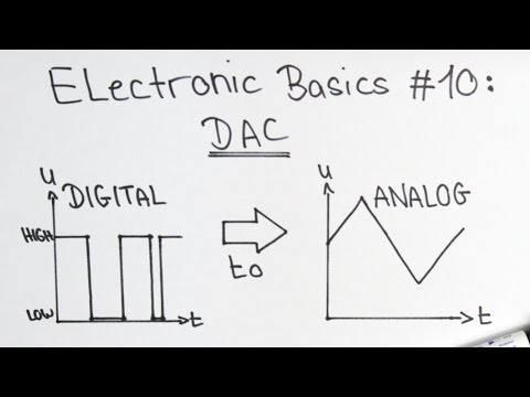
Electronic Basics #10: Digital to Analog Converter (DAC)
 0:07:27
MCP4725 DAC Arduino Tutorial | 12-Bit Digital-to-Analog Converter | Waveform Generator
 0:03:08
#705 12 Bit DAC Under the Microscope
 0:14:06
Using the MCP4725 12 Bit DAC with Arduino
 0:10:13
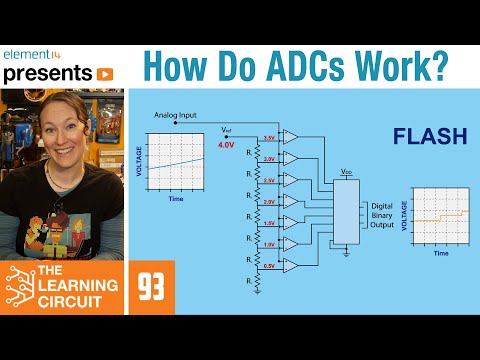
How Do ADCs Work? - The Learning Circuit
 0:06:48
Electronic Basics #27: ADC (Analog to Digital Converter)
 2:02:54
NASA ARSET: An Overview of SAR Data Sources and Tools, Part 3/3
 0:00:08
How to make Digital to Analog Converter using op-Amp
 0:05:12
Hardware modification for 12-bit DAC setting on 6dof ext board
 0:05:31
Analog Voltage from Raspberry Pi using MCP4921 12-bit DAC and SPI
 0:08:55
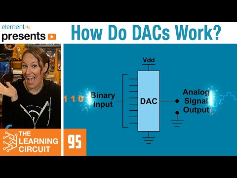
How Do DACs Work? - The Learning Circuit
 0:00:37
Successful test of 12bit PWM and 12-bit DAC module code
 0:33:01
MCP4725 12 bit DAC and SZBK07 DC-DC converter
 0:00:56
STM32F4 USB Audio Card using built in 12 bit DAC
 0:02:27
MCP4725 12-Bit DAC
 0:19:31
What is a 1-Bit DAC and How Does it Work?
 0:08:21
Assembly via Arduino - MCP4725 12 bit DAC
 0:00:58
🎛️ STM32 & 12-bit DAC MCP4921 #shorts #TechTutorial #STM32 #MCP4921 #arduino #dac
 0:01:33
Electronics: 12-bit vs 16-bit DAC
 0:26:38
ADC120 Evaluation Tools: 12-bit A/D Converter
 0:14:23
MCP4725 12-Bit DAC Interface to Raspberry Pi
 0:00:07
I2C Digital to Analog Converter
Комментарии