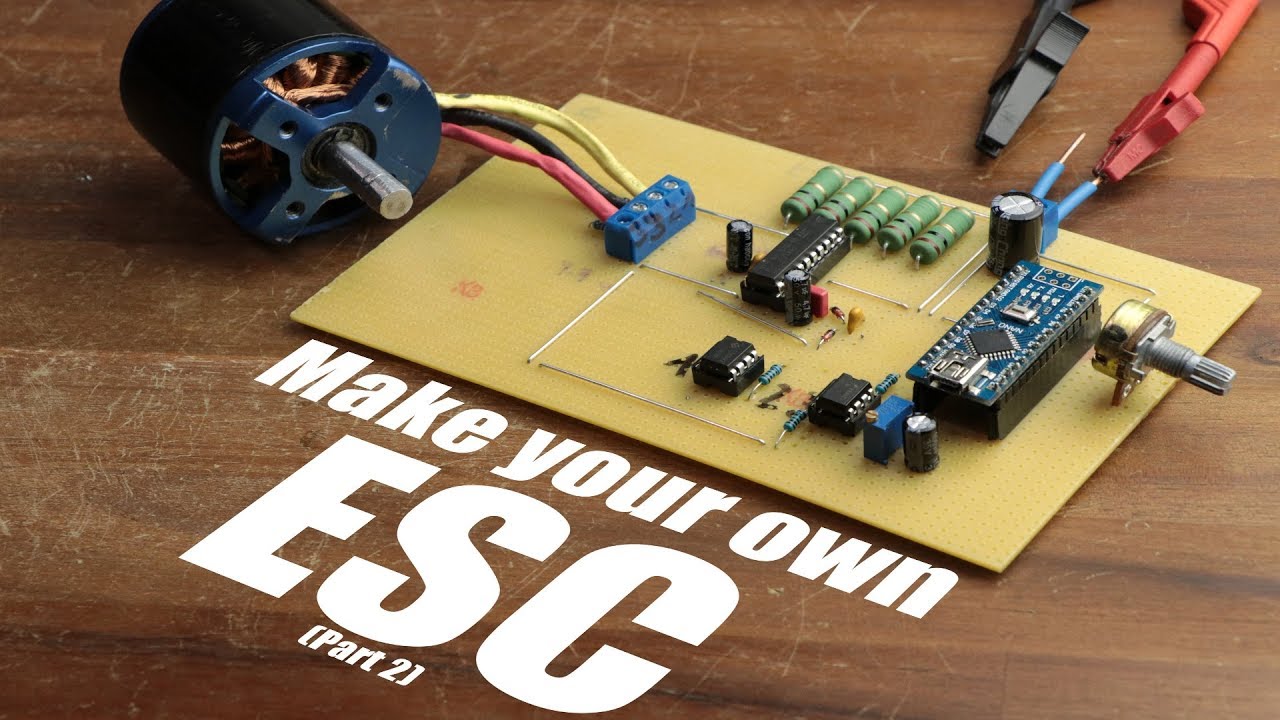
Make your own ESC || BLDC Motor Driver (Part 2)

preview_player
Показать описание

Parts list (affiliate links):
Aliexpress:
Ebay:

In this two part video series I will firstly demonstrate how a common ESC works and afterwards create a circuit consisting of an Arduino Nano, an L6234 motor driver IC and a couple of complementary components in order to make a DIY ESC.

Music:
In the Hall of the Mountain King, Kevin MacLeod
Killing Time, Kevin MacLeod
Рекомендации по теме
Комментарии
Автор

There shall come a day, where I will understand 100% of the content you post. But today is not that day!

braedanricketts
Автор

Many people claim that your videos are too complicated but I think that its the way to go. Well... Nobody thaught me about eletronics. I am learning because I want. The thing is that even if the subject requieres knowledge I will try to learn the "basics" and then come back to your videos. I think people should do that. A big part of what I know about eletronics comes from you, because I feel motivated to learn more and more so I can understand better the videos.You are a genius GreatScott! Keep this solid work. You inspired me and a lot of others. Thanks for the effort!

barbasbandas
Автор

I guess I should add my own comment. First, I just want to say this is a FANTASTIC video and I hope to see more. I dearly wish the people saying stupid things like "duh... just buy a ESC" would understand that the point is to learn and develop new ways of doing things, as well as to understand why ESC's work the way they do.

So... Let me be sure I understand:
1. You have to start "open loop" as far as position goes because you don't know where the motor shaft is... you just pulse it and switch the power back off when the voltage rises in the coil. You switch to the next coil after a set time. This is slow, because the A2D takes time, and the speed is pretty much just controlled by the frequency of the coil switches, not by the voltage applied, because you can't apply any more voltage without frying to motor. This is a "stepper mode". It should have good /holding/ torque, but the phases are too far apart to have anything like reasonable /detent/ or "pull in" torque like a regular stepper. The fact that you don't know where you are doesn't really matter because you can't drive the motor any harder anyway... if it's "skipping steps" against a load... oh well.

2. Once the speed is high enough for the magnet to induce a detectable back EMF voltage in the the third / undriven phase, we can use a comparator to trigger on that as our signal to switch to the next phase. At this point, the speed of the motor is controlled by the voltage we apply to the driven coils. As we back off the voltage, the motor moves less quickly to the next phase, and the back EMF spike appears later so we switch slower. Or we apply MORE voltage, not bothering to sense the voltage buildup in the driven coil because we know it won't get high enough to fry the coil or to pull more current than we can provide because it won't have time. The back EMF pulse happens quicker, we switch faster, and so the frequency and speed increase.

3. At some point, we probably can't sense the back EMF pulse quickly enough and we go into another open loop mode where we are just hitting the coils with everything we have and switching based on what we think the motor needs. If we start seeing the back EMF pulses again, then we can switch out of this mode and back down to mode 2. Or perhaps we still see the EMF pulses, but we must switch /before/ they appear. We are only looking for them as confirmation that the motor "caught up" with us. If we wait for the pulse, it's already too late to switch to the next coil. If we go ahead and switch, and the pulse doesn't show up when we expect it, then the load on the motor is too great and we have to slow our switching down a bit to avoid falling out of phase. I'm not sure this mode is actually necessary, but I think it may be why you are unable to get faster speeds.

All of that could be avoided if there was an encoder on the motor. In that case, we could simply pulse the coil that matched the current position of the shaft to get started, we could always know when the motor was ready for the next phase, and we would never lose the back EMF pulse as we ran slower or faster.

I'm really interested in the use of BLDC motors to make servos. I have a good encoder and some programming skills, so I hope to develop some ideas in this space soon. In the mean time, if you want a fun encoder to play with let me know. They are magnetic, non-contact, and still support very high speeds (28K to 75K RPM) and resolutions (4000 to 360 clicks) and... have a digital mode where you can just read out the current position instead of having to count the encoder pulses.

In any case, I'm completely fascinated! The use of the back EMF pulse is such a cool hack and seeing all the complexity of it from your exploration really helps me understand the limitations of this system.

THANK YOU!

JamesNewton
Автор

I am VERY glad that I found your videos. I'm building an vacuum cleaner robot and need to build simple, but powerful ESC. Now I finally understood how to do it. Brilliant!!!

madvasya
Автор

Did not understand anything, but still watched because hypnotized when GreatScott! is drawing his schematics ... Just marvellous !

tourdumonde
Автор

I am not sure if any one else has mentioned it, firstly appart form a very good tutorial, you are only running the motor in synchronous mode. Like a stepper motor, to get more speed you need to increase the frequency. It is not true brushless where the ESC only performs commutation as dictated by motor position and in such a way speed is governed by the voltage applied and the KV rating of the motor. Most ESC's start in stepper motor mode but as soon as the BEMF is sufficient to detect commutation state they switch over to full brushless, which is more efficient. and allows for faster operation. Thank you.

rotorrant
Автор

I LOVE that you show the troubleshooting process.

hjr
Автор

You can use hardware comparator that is in Arduino, at least for BEMF - you can attach virtual ground to AIN0 and phases to 3 analog pins and use internal multiplexer to choose which pin to use. It is much simpler and less error prone (PCINT aren't best solution for time-dependent tasks, and driving BLDC is such) than using external comparator. The only thing you have to have in mind is voltage levels, but simple voltage dividers should do the trick. Also you have to have in mind, that drone BLDS can operate at hundreds of amps, not like your small chip can deliver - 4A. Please tak that into consideration when selecting proper MOSFETs in the end of video.

domints
Автор

Love it "...instead of the measuring bullsh!t" at 5:30. Finding a way forward is what engineering is all about!!

coxsj
Автор

Excellent pair of videos! This was exactly at my comprehension level, and I think your pacing was spot on. Neither boring, nor too advanced/fast.

hovissimo
Автор

This video has saved me! I didn't understand why my motor didn't run continuously, and at last I found this video that is the only on youtube which explain why! Thanks a lot

JoseAntonio-mkor
Автор

These two videos were fantastic, even if I'm 4 years late saying so. Thank you for your hard work!

pete
Автор

I like that you took this problem from the very roots, but with better and smarter ic you can control in a much simpler way and more attractive for your viewers.

jaimecaballero
Автор

I absolutely love your videos! You have inspired me to learn more about electronic engineering and making something amazing. Keep up the great work!

shraiwi
Автор

Beautiful videos, you pay attention to every small detail. I like those close-ups where you are writting

Dolordemandibula
Автор

I keep coming back to your videos to see If things you say are starting making sense to me, If they do, then I know I've improved

wiredelectrosphere
Автор

Very well made video, thanks for sharing the steps you went through, and pointing out how hard it actually is to make a good ESC.

MarcMERLIN
Автор

Hi, Scott!

I love your videos! I really want you to make a sensored version, too! With IR2103 drivers and a hoverboard-like motor

Diygenes
Автор

Hey all! If anyone is thinking about building this, this circuit needs an additional resistor network! I just made something quite like this, using the same LM393 comparators, and my timing was looking really strange, and the speed/torque was a bit lacking. I'm using dual source, common ground to power my circuit, and the motor voltage is around 11v, the rest is at 5v. The motor acts as a voltage divider, making the motor common and coil leads around 5.5v, so what was happening was when the motor started to spin fast, the comparator inputs would get saturated over VCC and on the way back down take a fair bit longer to switch low, making the next step happen much later than it should. I added a resistor network (10k) at the coil sense leads to half the voltage, and then connected the common with 1ks. Now my voltage sits in a happy place between VCC and ground, and the timing is looking spot on. Have fun!

davel
Автор

Hi Scott, thank you for your inspiring videos. This video has remind me two salvaged washing machine motors that I would like to use for something useful. A video series on speed control for this universal motors would be really great, if made it by you. (and I bet would be pretty interesting for all us beginner makers that want to build some useful tools). Thanks again for your videos, I really appreciate it.

thlchmst