filmov
tv
Example 2.1 || The Ideal Transformer || Transmission Line Losses || || (English)(Chapman)
Показать описание
Example 2.1 || The Ideal Transformer
EM 2.3 (English)(Chapman)
00:00 - Ideal Transformer
01:00 - Turn Ratio
03:00 - Phasor voltage, current & turn ratio
03:35 - Power in Transformer
04:10 - Impedance Transformation
07:25 - Example 2.1
Example 2.1 || The Ideal Transformer || Transmission Line Losses || || (English)(Chapman0
oin us as we delve into Example 2.1, focusing on the Ideal Transformer and Transmission Line Losses, with insights from Chapman. This video provides a comprehensive breakdown of the Ideal Transformer concept, exploring its significance in electrical systems. Gain a deeper understanding of transmission line losses and the role of ideal transformers in power transmission. Stay tuned to uncover the mysteries behind Example 2.1 and the ideal transformer!
Hashtags:
#Example2.1 #IdealTransformer #TransmissionLineLosses #Chapman #ElectricalEngineering #Explained #Breakdown #Simplified #EngineeringInsights #TechTalk
SEO Tags:
Example 2.1, Ideal Transformer, Transmission Line Losses, Chapman, Electrical Engineering, Explained, Breakdown, Simplified, Engineering Insights, Tech Talk, Power Transmission, Electrical Systems, Ideal Transformer Analysis, Transmission Loss Calculation, Engineering Concepts, Electrical Losses, Chapman Example, Transformer Efficiency, Engineering Education, Transmission Line Efficiency, Electrical Circuits, Ideal Transformer Design, Engineering Students, Power Loss Reduction, Electrical Components, Transmission Line Theory, Ideal Transformer Operation, Electrical Theory
This video describes basic features of Ideal transformer.
Here we also discuss solved example 2.1from the book Electrical Machinery Fundamentals.
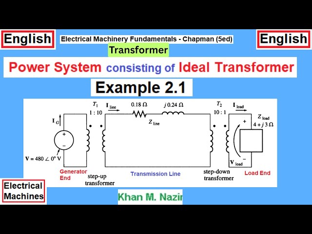
Example 2.1: A single-phase power system consists of a 48OV 60-Hz generator supplying a load Z_ = 4 + j3 ohm through a transmission line of impedance
Zline = O.I8 + jO.24 ohm.
Answer the following questions about this system.
(a) If the power system is exactly as described above (Figure 2-6a), what will the
voltage at the load be? What will the transmission line losses be?
#ElectricalEngineeringAcedemy
EM 2.3 (English)(Chapman)
00:00 - Ideal Transformer
01:00 - Turn Ratio
03:00 - Phasor voltage, current & turn ratio
03:35 - Power in Transformer
04:10 - Impedance Transformation
07:25 - Example 2.1
Example 2.1 || The Ideal Transformer || Transmission Line Losses || || (English)(Chapman0
oin us as we delve into Example 2.1, focusing on the Ideal Transformer and Transmission Line Losses, with insights from Chapman. This video provides a comprehensive breakdown of the Ideal Transformer concept, exploring its significance in electrical systems. Gain a deeper understanding of transmission line losses and the role of ideal transformers in power transmission. Stay tuned to uncover the mysteries behind Example 2.1 and the ideal transformer!
Hashtags:
#Example2.1 #IdealTransformer #TransmissionLineLosses #Chapman #ElectricalEngineering #Explained #Breakdown #Simplified #EngineeringInsights #TechTalk
SEO Tags:
Example 2.1, Ideal Transformer, Transmission Line Losses, Chapman, Electrical Engineering, Explained, Breakdown, Simplified, Engineering Insights, Tech Talk, Power Transmission, Electrical Systems, Ideal Transformer Analysis, Transmission Loss Calculation, Engineering Concepts, Electrical Losses, Chapman Example, Transformer Efficiency, Engineering Education, Transmission Line Efficiency, Electrical Circuits, Ideal Transformer Design, Engineering Students, Power Loss Reduction, Electrical Components, Transmission Line Theory, Ideal Transformer Operation, Electrical Theory
This video describes basic features of Ideal transformer.
Here we also discuss solved example 2.1from the book Electrical Machinery Fundamentals.
Example 2.1: A single-phase power system consists of a 48OV 60-Hz generator supplying a load Z_ = 4 + j3 ohm through a transmission line of impedance
Zline = O.I8 + jO.24 ohm.
Answer the following questions about this system.
(a) If the power system is exactly as described above (Figure 2-6a), what will the
voltage at the load be? What will the transmission line losses be?
#ElectricalEngineeringAcedemy
 0:19:51
Example 2.1 || The Ideal Transformer || Transmission Line Losses || || (English)(Chapman)
 0:22:54
Ideal Transformer || Example 2.1 || Load Voltage, Transmission Losses || EM 2.3 (Chapman) (Bengali)
 0:04:39
Circuits I Example Using Ideal Transformer - Circuit Analysis
 0:07:48
Circuits I: Example Using Ideal Transformer
 0:03:34
Ideal Op Amp Example #2 - Signal Processing #02
 0:19:44
Ideal Transformer || Transmission Line Losses ||Example 2.1(Chapman) || EM 2.3 (E)(Ch)
 0:02:25
Thermodynamics: Ideal Gas Law. Level 2, Example 1
 0:05:06
Ideal Op Amp Example #1 - Signal Processing #01
 0:07:27
Circuits 1 - Ideal Op-amp Example
 0:15:13
Using the Ideal Gas Equation: Example Problem #2 (Part 1)
 0:11:42
Example of Non-Principal ideal in Z[x]
 0:10:49
Thermodynamics - 3-6 Ideal Gas Equation example 2
 0:10:13
Chapter 9: Property Changes of Ideal Gas Mixtures Example
 0:05:19
Example 15.3-2 - Mixing of two ideal gas streams [Transport Phenomena : Heat Transfer]
 0:04:56
Example Using Ideal Transformer
 0:02:40
HTPIB13F Ideal Gas Example 2
 0:01:38
Thermodynamics: Ideal Gas Law. Level 2, Example 2
 0:31:12
rs simulation learning journal 8 - uom example 2 ideal gas equation
 0:04:46
Ideal Gas Law Example 2
 0:02:55
Ideal for (Note groups: 4-1-5-2) in Example 13 - Instant Shredding Picking Workout by German Schauss
 0:12:11
Ideal Op-Amp Inverting Amplifier Example
 0:21:17
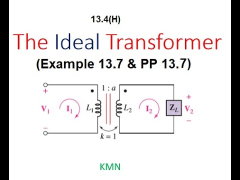
Ideal Transformer || Example 13.7 & Practice Problem 13.8 || ENA 13.4(1)
 0:03:59
Ideal Gas Law Example # 2
 0:03:47
Ideal Gas Law (Example 2)
Комментарии