filmov
tv
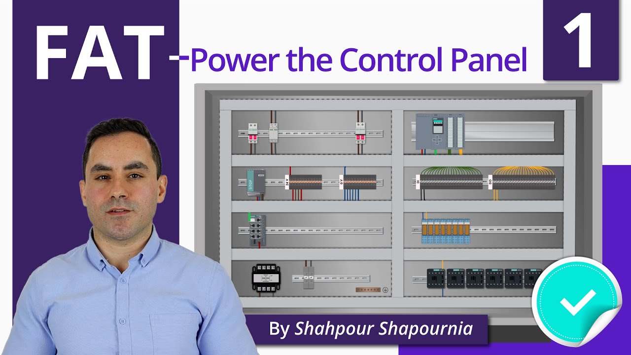
Factory Acceptance Test Explained - Part 1 | Power the Control Panel
Показать описание
=============================
▶ Check out the full blog post over at
=============================
⌚Timestamps:
00:00 - Intro
00:35 - Acceptance Test
01:56 - FAT example
02:52 - Step 1) Power the control panel
03:46 - Point #1
04:23 - Point #2
04:38 - Step 2) Switch on all the devices in the control panel
=============================
In the world of industrial automation, a Factory Acceptance Test or FAT is simply a test for a newly manufactured control system that takes place at your factory or your workshop before you ship the control panel to the customer.
With a Factory Acceptance Test, you make sure that everything works properly before you deliver a control cabinet to a customer.
Let’s explore FAT a bit further through a practical example.
Let’s say that you are a company that designs and implements industrial control systems. These control systems often come in the form of a control panel built into a control cabinet.
You’ve built the control panel and now it’s ready to ship to the customer. But before you ship it you want to make sure that everything works properly. The last thing you want is to ship it to the customer’s site only to find out that things are not quite working the way they should.
Consequently, you will have to spend countless hours at the client’s site solving issues that you could have easily taken care of before shipping the control panel. So, as the name suggests, a FAT is completed at the factory.
Now you may be wondering, where should I start? What do I need to test? Well, I will show exactly that through a step-by-step example.
Step 1
As the first step, you need to connect the power to your control cabinet and turn it on. We have a main circuit breaker for every control panel. This is where the power comes into the control panel for all of the devices.
To let the electricity come into the panel, you need to connect the power to the topside of the circuit breaker. This is a wire that comes from outside of the panel.
You connect it to the circuit breaker only for testing and once you are done and want to ship the cabinet, you simply disconnect the wires from the topside of the circuit breaker.
The power that comes into the panel can be anywhere from 480 volts AC to as low as 120 volts AC depending on where you are and the country you are based in.
Once you have the power connected to the topside of the circuit breaker, you can switch it on for the power to flow to the control panel.
Although this seems a very simple process so far, there are two important points that you need to consider when trying to power on your control panel:
#1
The circuit breaker generally has a disconnect on the outside of the panel that allows you to shut off the power. Before you want to connect the cable to the main circuit breaker inside the panel make sure that you have disconnected the power using this switch.
Don’t take the hot power into your hand and try to connect it to the circuit breaker. This is dangerous.
#2
The second point to consider here is that when you switch off the circuit breaker, the topside of it will still have power. So, again, before you want to disconnect the power you need to make sure that you have disconnected the power from the outside of the panel.
Step 2
Now that you have connected the power cable to the control panel and switched on the circuit breaker, you also need to switch on any other breakers or fuses that you may have on the way to power the PLC and the other devices.
In the end, I also switch on the PLC power supply as well. The PLC power supply could be installed on the same rack as the PLC or somewhere else on the panel. We may have one, two, or three power supplies on our panel depending on how many devices we need to power on in the control panel. The more devices we have, the more power we need to turn them on.
=============================
Missed our most recent videos? Watch them here:
=============================
To stay up to date with our last videos, make sure to subscribe to this YouTube channel:
=============================
=============================
#RealPars #FAT #Control_Panel
 0:06:28
Factory Acceptance Test Explained - Part 1 | Power the Control Panel
 0:06:35
What is Factory acceptance test FAT!!
 0:07:08
Factory Acceptance Test Explained - Part 2 | PLC Digital I/O Test
 0:06:27
Factory Acceptance Test Explained - Part 3 | PLC Analog IO Test
 0:01:42
Factory Acceptance Testing- What is the Purpose of FAT? Why is it Necessary to Perform FAT?
 0:09:09
Factory Acceptance Test Explained | FAT | SAT
 0:01:11
What is a Factory Acceptance Test (FAT)
 0:03:48
Factory Acceptance Testing
 0:00:55
Modern Times: A sequence with many gears (factory scene) #chaplin #javascript #observable #shorts
 0:36:15
ABB TechTalks: Redefining Factory Acceptance Test (FAT)
 0:01:42
Factory Acceptance Testing- Who is often required to prepare a FAT Plan?
 0:01:42
Factory Acceptance Testing- Define FAT. Why is it Essential during the Procurement Phase?
 0:01:44
5 Steps to a Successful Factory Acceptance Test with Frain Industries
![[ English] What](https://i.ytimg.com/vi/nDVskKiKcJU/hqdefault.jpg) 0:03:54
0:03:54
[ English] What is FAT ? / Factory Acceptance Test
 0:04:03
Factory Acceptance Test (FAT) 820.75 & ISO 13485 § 7.5.6 (Executive Series #68)
 0:11:21
Switch-gear Factory Acceptance Testing-What is it?
 0:01:43
Virtual Factory Acceptance Test (FAT)
 0:01:11
Factory Acceptance Test (F.A.T.) of a pharmaceutical process equipment.
 0:00:28
Factory Acceptance Test
 0:01:17
Thermo Fisher Scientific Factory Acceptance Test (FAT)
 0:05:30
How to Conduct Factory Acceptance Tests (FAT)
 0:00:31
Factory acceptance testing (FAT) - options for select low- and medium-voltage products
 0:03:03
Virtual Factory Acceptance Tests | KROHNE
 0:01:42
Factory Acceptance Testing - When does FAT take place?
Комментарии