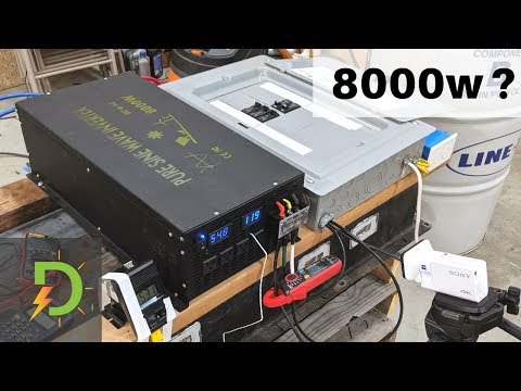
Cheap 8000w Reliable Electric Inverter, Full Load Test, Review

preview_player
Показать описание

Part 2 Video testing the new updated version of 8000 watt inverter from Reliable Electric. This inverter outputs a pure sine wave, 120 volts AC. At 34 pounds it's light enough for mobile applications. I'm powering this inverter with my new 48 volt lithium battery that I made from a used Smart Fortwo EV car.

In the previous video I showed this inverter could handle power tools and compressor loads. Awesome! This video is dedicated to doing a full load test.

1. Can it reach 8000w?
2. How long can it stay there?
3. How hot does it get?
4. Do the batteries get hot?

In order to do a full load test I have wired in a sub-panel and electric heaters.

This new version works way better than the first version. Reliable Electric has upped their game.
-----------------------------------------------------------------------------------------
Reliable Electric's E-mail about the live ground:
"And For the voltage , the voltage from Line to Ground and Neutral to Ground is not the true voltage, there is no correct from them.
This virtual voltage has no effect on the usage.
If you measure it during loading , it will be zero at that time.
So please feel free to use it ."
----------------------------------------------------------------------------------------

This inverter is usually called HF, or high-frequency. That's because there is no massive transformer inside. Usually HF inverters can't handle large surge loads such as motors and compressors. So that's exactly what I used to test it!

Reliable Electric is also known as "WZRELB" I have seen it sold under both names.

Sometimes this inverter is available on Amazon, sometimes Ebay. The links sometimes change, sorry about that.

There are (6) 48 volt batteries all wired together in parallel. Each battery has it's own BMS board for safety. BMS stands for battery management system.

This lithium battery came out of a 2013 Smart Fortwo EV (electric vehicle). It will be used in my DIY Powerwall for back-up power if the grid goes down. Off-Grid.

Thanks for watching. If you would like to help support the channel please check out Patreon, or use an affiliate link. Thank you.

“As an Amazon Associate I earn from qualifying purchases.”

Inverter in video was provided by Reliable Electric.
Рекомендации по теме
Комментарии
Автор

It was doing over 8000 Watts on the input side at 9:30 minutes. Lots of rating are taken from a specific test or measurement they decide, to meet the highest numbers to impress buyers. So at 7068 Watts, your input is at 8143 Watts.
Its says its an 8000 Watts inverter it does not mean that it outputs 8000 Watts it's Max rating witch will be the input side will reach 8000 Watts. That means that at 8000 Watts with an 87% efficiency will deliver 7000 Watts of usable output power.


Great Video keep up the good work!

stephtronix
Автор

David, I've found that situation with the odd noise to be a result of the type of load being run from the inverter. Heat guns and space heaters often use a diode in series with the element to allow for a "low setting". The diode half rectifies the sinewave basically halving the output power that you'd get from high power. This makes the inverter work overtime because even though the actual output power may only be 750 watts, that 750 watts is being drawn only from the positive or negative half of the waveform. This forces a significant imbalance on the mosfets trying to drive the output stage causing all sorts of crazy noise. I've always avoided running a device like this on low power setting from an inverter for fear of damaging the inverter. Hope this helps

carlsch
Автор

The voltage you measure between neutral and ground has to do with how the inverter is constructed. There are two common constructions that give this:
1) one output gives a square wave, the other side a 'inverse-rectified' sine wave, L-N is then a complete sine wave.
2) [better] both outputs give a 180 degree out of phase signal (H-bridge driving a symmetrical filter)
The fact that you measure different voltages between both wires weakly suggest configuration 1, but without a scope you can't really know.
Assuming the case is grounded, this is not really a problem, although some appliances expect a neutral that is very close to ground potential, they won't work. Connecting something (eg, a panel) that bonds neutral to ground will short out the inverter.

The strange sound is the internal 48V->200/400V DC/DC converter going into current limit mode. The driver PWM is varying a bit chaotically and some pulses may be skipped. This causes the transformers to make a crackling noise. It is harmless, but does mean you are at more or less the max output power. You can draw a bit more, but the output waveform will not be a sine anymore (peak power at top of the sine can't be provided). The RMS output voltage will also be dropping, as you saw.

BertoldVdb
Автор

I am definitely not familiar with this model inverter. I can say that my 2000 watt Honda inverter generators measured the same 60vac hot to neutral and neutral to ground. The reason as explained to me was for the different NEC requirements for RV’s. I was told by the Honda dealer to tie the neutral and ground together. It worked well and now I have 120 vac load to neutral and ground and obviously nothing neutral to ground. I would in your situation, specifically get a recommendation from the inverter manufacturer before tying your neutral and ground together.

Thank you for your presentation. Very relevant information and well presented.

ricknelson
Автор

Well done evaluation David! I agree that type of inverter could be adequate for a portable site supply. It should be sufficient for running any 2-pronged, ungrounded tools. But I wouldn't run it at over 5000w. And any sustained load for more than 30 mins, I wouldn't go over 4000w, unless you want to be replacing boards every few months. Reliable is notorious for making inverters that are way under-engineered for the ratings they apply to them.
That humm you were hearing at 6800+ watts was likely the sinewave being clipped at the top and bottom and essentially putting a partial square wave through those undersized coils.
If the inverter is able to even get close to 80% efficiency at those higher wattages that would mean that 20% of 7000w is being burnt off as heat. So you have the bonus utility of at least a 1400w space heater that your fans are working so hard to extricate.
Well done, keep up the good work!

aspendell
Автор

Great test, 7000w from an 8000w inverter is OK by me. u can't run 8000w continual but 7000w ur OK is nice.

omoleogedengbe
Автор

I’d like to see your thoughts on running this unit with the larger gauge wire. I agree with your opinion that those wires seem undersized. Love your channel!

nickdepuy
Автор

David, you should look into DC direct power. There is a house up here in the mountains near me that was recently built. The entire house runs off DC voltage and its been fun picking the guys brain. Basically, he designed the house with 5 voltages. The main battery bank is run as a 192v DC bank off Sinopoly cells with most of the capacity stored. The house is wired for 192v DC, but in each room he designed it so in each room there is a small panel in the wall that houses small DC circuit breakers for 192v, 96v, 48v, 24v, and 12v DC along with a smaller size battery bank mounted in the panel with some smaller sinopoly cells. He has pigtails running off the smaller 192v bank in each room that runs to each voltage breaker equally to draw down the battery equally. He did it this way to reduce the distance for high amp short burst draws off the system. Then everything in the house has been changed to run off DC voltage or rewired to run off DC. The air conditioner is a mini split system designed to run off 96v, the frig in the kitchen is 192v (170v), the stove is 48v induction unit... basically, he converted his entire life over to DC voltage and now has no inverters in the system to worry about for his entire house except for a handful of items he could not convert due to warranty or due to difficulty, so he uses smallest AC microinverters for them separately to reduce the vampiric losses. He found that most electronics they convert the AC voltage to DC voltage internally, so he would measure out what voltage the device was converting to internally, run a jumper wire with the correct resistance to drop the voltage to the proper voltage and it run it off DC voltage directly with a new power cord. For example, when he was looking into his refrigerator, he found that it converted 120v AC to 170v DC before it went into the mainboard and converted to the various other voltage levels it needs to run, so he just wired it directly, feeding the 170v directly from the 192v DC circuit.

williamhustonrn
Автор

I must say I have just finished watching the last 30+ videos today. And I found them very informative and interesting on all your solar and power wall stuff. Thank you for sharing it all.

ScaldaYT
Автор

I bought a 1500 watt 120 volt heating element for the water heater to run it on generator. Come to find out the 250 volt 4500 watt element was 1300 watts on 120 volts. The resistance was 13 ohms on the 1500 watt and 15 ohms on the 4500 watt. Conclusion was to just wire 120 volts to hot-water heater and leave it as is. This works perfectly on the small 3kw genset.

DallasAya
Автор

It's a reliable 4000watt inverter.

tommanley
Автор

My Reliable 1500W does the same thing, showing 62V on each ground-neutral and ground-hot. I think they made a 120V split phase inverter (technically having two hots and no neutral) rather than a 120V single phase inverter. That would scare the heck out of me wiring to an actual outlet. G+N are supposed to be at the same potential. Great test though!! Stick to the AIMS. Lol

LithiumSolar
Автор

awesome video (as always), i liken this to speakers and amps, my dad always bought 150watt speakers but with a 100watt amp, so the speakers would tick over nicely when the amp was turned up full. bizare analogy i know but if you wanted 6500w of power, buying an 8000w inverter would make sense, i wouldnt want to run anything at its max spec

MagivaIT
Автор

To draw 8000W off a 12V lead acid battery, you'd need at least (2) 8D deep cycle batteries in parallel, and some very heavy gauge wires. At 8000W you'll be pulling around 750 amps.

electronicsNmore
Автор

Your review is appreciated . Seems as though most DYI's are running installs at 50% of capacity rate . Test Test Test

Nostrildomus
Автор

18:35 this is perfect spot for "Technology Connections" guy to cut in to explain in great detail what was making that noise inside the inverter

JR-njle
Автор

I use this for my shed to use a small welder and a mini fridge with 0 gauge wire, 200watt panels, a 200 amp class D solar battery and it works terrific.

mega-hbre
Автор

Great job David. As always, I commend your performance. As a retired Engineer with more than 40 years in Practice, my ears have become "fine tuned" to identify and diagnose equipment based on the sounds that I hear. In this case, I think I know where the noise is coming from when you attempted to exceed 7000 watts. I believe that the sound is being made by either a HIGH Voltage Leak or Arcing which may occur constantly or only at a specific resonant frequency. I suggest that you perform the following test and fix to confirm the source and eliminate the noise. This testing is based on the process of elimination and works on lots of Electronic devices that make this kind of noise including your TV. This cheap repair will also bring the Voltage back up to spec when you exceed 7000 watts. The first variable that you'll want to eliminate and replace is the last load that you placed on the Inverter. In this case replace the Heater with a totally different type of device that will draw the same wattage. This may be all you need to do to confirm the source of the noise.
If it works, it means that you hit a resonant frequency and the Electronics in the Inverter are not compatible with the Heater in combination with the other loads. If that doesn't work...

The following is what I'd like to see you do. Reproduce this video as a diagnose & repair video using the following steps to identify both External and Internal HIGH Voltage Leaks and to repair them.
Step 1
Remove the Top Cover before you bring the Inverter up to 7000 watts or more however, this time with the lights in the room turned off (this will make it easier for you to visually identify the source of the Voltage Leak). If in fact, it turns out to be an external leak you should be able to see the arcing in the dark when the lights are turned off. The Arcing will look a tiny illuminated blue thread of Lightening jumping out of the source and onto another surface.
Step 2
If you do not discover the source with the top cover removed then, proceed to remove the side and bottom covers one at a time and repeat the test one time for each.
Step 3
If you've located the leak, you can try to repair it by covering the surface that is releasing the Electrical Arc with a thick layer of Clear RTV Silicone, the thicker the better. I've used this repair on many Electronic devices including a High Voltage Capacitor that had burned a hole through its exterior casing and was releasing a High Voltage current that was arcing with other parts of the Chassis on a Sony Trinitron Color TV. That TV was still working 20 years later until we gave it away and upgraded to a Flat Screen TV.
Step 4
If you've completed Step 3 and cannot visually identify any external arcing then the next thing to do is to look for a source of Internal arcing. You accomplish this by listening to each of the components, first with your Ear to identify and narrow down the general area where the noise is coming from. Once you've narrowed down the general area, you then probe each of the surfaces and components with a non conductive Stethoscope (if you don't have a Stethoscope you can try holding a wooden dowel or other non conductive material against your ear and using the other end as a probe). You can also purchase a cheap Automotive Stethoscope that has an Aluminum Probe for about $10-$12 at most Auto Parts Stores and then cover the Aluminum Probe with a Rubber Insulator as long as the insulation at the tip is hard so that it can mechanically conduct and transmit the sound. I used clear Vinyl Aquarium Tubing to cover the Aluminum Probe and then used a Hard Plastic Cap at the end. I would actually start by Probing the Capacitors because when overloaded they arc and slowly burn a hole through each layer of insulation and then through its exterior case. An Internal Leak will eventually burn its way through the Component and culminate by either becoming an External Leak/Arc or it's possible that the Inverter will either continue to operate at a reduced output or completely shut down instead,

That's about it. It's pretty simple and I'm sure that you will enjoy your newly acquired diagnostic skills so much that, you will begin probing everything around you.
Thanks Again,
Nick

nickcarozza
Автор

I don't think I would lug all that equipment around in the middle of a field to use battery power. A portable generator works great and they usually have a wheel kit. I am impressed by all the batteries and inverters you have and have tested.

onefixitman
Автор

Great video I enjoy learning along with you. I love my PowerJack LF 48v 15000 splitphase. Runs entire house, just got to keep it cool.

lifeadventures