filmov
tv
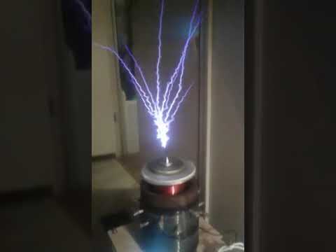
Vacuum Tube Tesla Coil Topic [Part 1 /how it works (roughtly)]

Показать описание
Hey.
Thats my first video, trying to explain a littlebit the function of the oscillator circuit.
More about the tuning etc. will follow.
#teslacoil
#electronics
#howtomake
Thats my first video, trying to explain a littlebit the function of the oscillator circuit.
More about the tuning etc. will follow.
#teslacoil
#electronics
#howtomake
 0:27:41
Vacuum Tube Tesla Coil Topic [Part 1 /how it works (roughtly)]
 0:00:12
Full Vacuum Tube Staccato switching Vacuum Tube Tesla coil!
 0:00:07
gu5b vacuum tube tesla coil
 0:00:15
😍 Music Tesla Coil experiment #teslacoil #plant
 0:01:44
Vacuum Tube Tesla Coil With 3X2500F3 TX Tube Works!!!
 0:01:43
Vacuum tube Tesla coil 1080p60!
 0:21:04
DIY Vacuum Tube Tesla Coil With 3X2500F3 || Full Build
 0:06:04
High Powered Tesla coil with Vacuum Tubes
 0:05:21
Vacuum Tube Tesla Coil / GU-81m
 0:04:44
750 mm Plasma Tubes and Vacuum Tube Tesla Coil
 0:05:45
Tube tesla coil #1
 0:00:11
vintage tesla coil
 0:00:31
Spark gap as staccato vacuum tube tesla coil
 0:02:00
Duel of the Teslas
 0:12:35
Vostok 3.0 Vacuum Tube Tesla Coil Demo + Theory Of Operation
 0:02:26
Ian's Vacuum Tube Tesla Coil - True Colour HD
 0:01:09
INSANE 30,000 Watt Tesla coil making HUGE sparks! DRSSTC
 0:00:55
LARGEST TESLA COIL IN THE WORLD (3 million volts discharged)
 0:54:06
The Secret Life of Lightning: The Science of Giant Tesla Coils | Greg Leyh
 0:00:28
Power arcs on my vacuum tube tesla magnifier.
 0:00:18
GU-48 Tesla coil. #Shorts
 0:02:31
Tiny Tesla Coil vs Spectrum Tubes ϟ gAdgetify
 0:13:05
The Phanotron Tube in a Dielectric Field of a Bipolar Tesla Coil
 0:31:55
How a Tesla Coil Works: Complete Explanation of DRSSTC Principles & Power Electronics
Комментарии