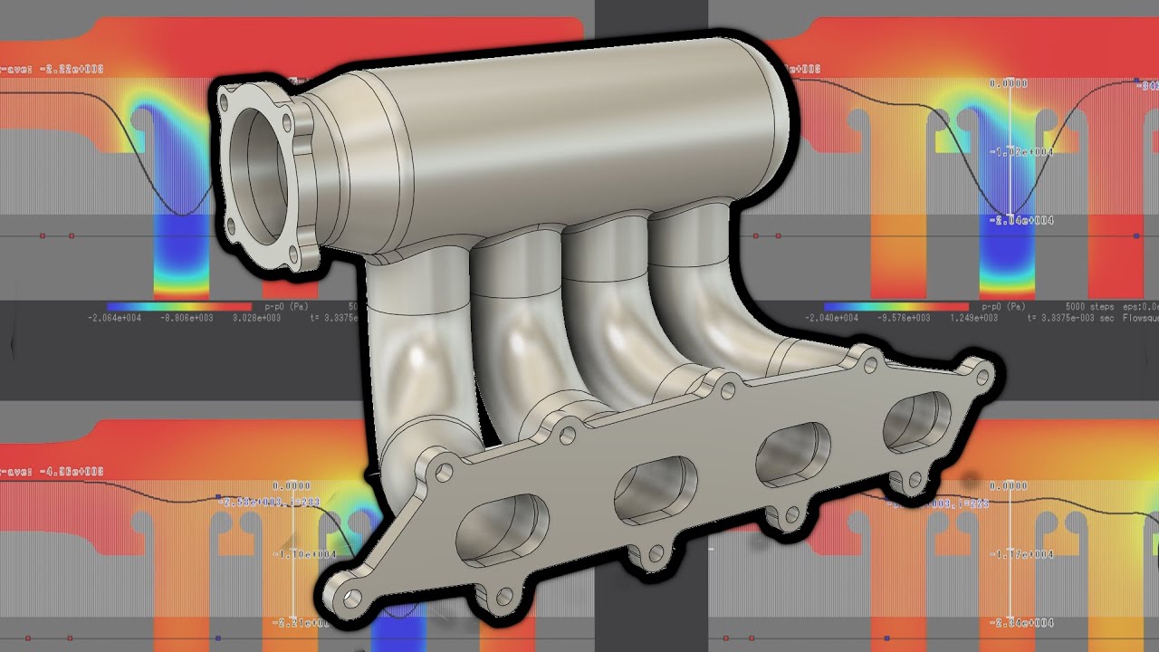
Intake Manifold CFD Modeling for Power - Plenum and Inlet Radius Design

preview_player
Показать описание
I want to thank Yuki Minamoto for developing the excellent, easy to use, software: FlowSquare

I’m glad to hear any thoughts or criticisms. So please comment below. Also, if you have any ideas for CFD tests you’d like to see, comment that too!
Рекомендации по теме
Комментарии
Автор

holy shit how can this video only has 1k view? it deserves way more. Love your video man !

kitni
Автор

From what little I've read very recently; You need to have a tapered plenum that shrinks down from 1 to 4, and the throttle body inlet also needs to be angled away from the runners toward the "roof" in relation to them. This makes it more even.

Drunken_Hamster
Автор

Cool video. Like you said, intake and exhaust manifolds are a very chaotic system once scavenging / resonance / pressure waves etc are accounted for.

Makes me wonder what kind of modelling and analysis tools the OEM's and race teams get to play with?

I imagine the formula 1 manufacturers have pretty robust modelling software, rather than just throwing millions of dollars in prototype parts at the car and seeing what sticks

Jason-fpvi
Автор

Your video from two years ago was recommended to me. Checked for the updated version and saw it was done yesterday lol

Donyce
Автор

Taper the plenum going from 1st to 4th cylinders. Reduced volume = more speed. This will let you compensate for the 3% loss. May be more difficult to fabricate though, since it will not be a simple cylinder.

guest
Автор

I love your to perform a CFD with a taper on the runners and see their effect please.

DATC
Автор

Another thing is I've found on bench testing the throttle plate should be modeled (being open and in the air stream) and the inlet pipe going into it can have a significant difference on manifold distribution. ( Length and angle of approach to TB etc)

Christdeliverme
Автор

Would like to see CFD of a dual plenum intake manifold.
Or a video on how to do CFD?

HAZZA
Автор

Great video, thank you! Really surprised to see that raised velocity stacks performed worse than integrated ones. I always thought that rasing stacks is important to improve flow because of issues with boundary layer.

MAV
Автор

Instant subscription! This is a topic close to my heart and hearing someone say resonance is a factor is great! I have got a question though How far has cfd developed? Have you seen or has anyone out there got the ability to simulate cam profile and resonance along with the firing order as too often hear people talking about cfm of intakes or heads, with little or no reference to resonance and the fact it’s filling a cylinder with a moving piston, having seen higher hp from lower flowing setups I think that 4 stroke resonance although not as important as two stoke should be considered all the same, no doubt the top end of developers would like f1,

needmoreboost
Автор

Good video, decent design.
Do you have any design suggestion for ensuring the rearmost ports get a more equal flow? A tapered design for the volume/plenum is the usual solution.
I've been doing a lot of reading and research on inlet manifold design, Helmholtz resonance and David Vizard's substantial work in this field. I understand a 7º taper and bellmouth radius of 1/4 of the port entry diameter should yield a gain in flow of a few percent. The port entry radius is also better slightly flattened... or the surface around (and dividing) each port entry more semi-eliptical rather than semi-circular.
Could you repeat this with above recommendations to compare the improvement?

ChrisBSX
Автор

I'd like to explore a single cylinder high performance high rpm engine with a resonant airbox idea.

HPRaceDevelopment
Автор

This is the another level of tuning. Am searching for the answer for my question and finally got it.

With this same setup na vs forced induction comparison. Can you do it?

blkdna
Автор

Tom! You are honestly the only person I've been able to locate that knows how to operate Flowsquare+ to a high level. I have a complete understand of setting up models, but I do have some questions for you regarding your simulations:

1. Did you define the inlet and outlet by aligning the .bmp to the STL you imported? Seems to be the only way for me to get this to work.

2. Are the animations from Paraview? Any tips on that? That portion of this entire process seems very unrefined.

3. Lastly; am I not mistaken in that exports are defined every N # of time steps? It appears your animations are every 50, yes? That is controlled via param.txt, right? I am admittedly confused with how to export data from this software. It seems very powerful after getting multiple simulations to run.

jasondean
Автор

but if the engine is running it wouldnt have atmospheric pressure in the plenum. that would be on the opposite side of the tb. in the plenum it would have a partial vaccuum if engine is running. dont know how much itll affect results, but it might

dee
Автор

hi! I'm a bit late to the party - amazing video, thanks for the CFD analysis - I just have to mention, why do you think every race engine manufacturer and OEM goes for full velocity stacks then? they must have the tools to figure this out. The ferrari 458 has full velocity stacks inside the intake manifold just like honda does with the rsp and well they are some of the best intake manifold designs ever and make upwards of 120 hp per liter, so I'm guessing a full velocity stack IS better?

AwesomeBoss
Автор

Is there a way to get a glimpse on the Boundary conditions CFD setup ?

osamamaddani
Автор

Can you do a video for a centre feed style plenum?

jongillies
Автор

Can you do one for motorcycle plenum? For example for hayabusa, because there is not too much space, so we can’t do long runners, so we never know if we need a big plenum or smaller and big runners

DanCycles
Автор

Would tapered intake runners make a difference? Thx!

ZebulonAirRacing
welcome to shbcf.ru