filmov
tv
TTL Serial Communication Explained | Part 2

Показать описание
🤩 FREE Arduino Crash Course 👇👇
***Get the code, transcript, challenges, etc for this lesson on our website***
SERIAL READ VIDEO:
SERIAL BEGIN:
We designed this circuit board for beginners!
SHOP OUR FAVORITE STUFF! (affiliate links)
---------------------------------------------------
Get your Free Trial of Altium PCB design Software
We use Rev Captions for our subtitles
Arduino UNO R3:
Budget Arduino Kits:
Multimeter Options:
Helping Hands:
Soldering Stations:
AFFILIATES & REFERRALS
---------------------------------------------------
FOLLOW US ELSEWHERE
---------------------------------------------------
SO WHAT IS THIS U(S)ART THING?
Many microcontrollers come equipped with a simple way to communicate serially – using a USART. USART stands for Universal Synchronous/Asynchronous Receiver/Transmitter.
Wow – that’s one heck of a name! But let’s dive in – it actually way more reasonable than at first glance.
A USART is a piece of hardware. You’ll find it as either a stand-alone integrated circuit, or built right into a microcontroller.
An Arduino UNO for example uses an ATMEGA328P microcontroller which has a built-in USART.
This built-in USART (which uses the RX/TX pins on the Arduino) can send bytes of data serially to a different microcontroller on the Arduino UNO board, the ATMEGA16U2, which is used to handle the serial communication over USB.
USARTs allow us to take data in parallel from one device, convert it into a serial transmission, and then transform it back again into parallel data.
Now I want to draw attention to the Synchronous/Asynchronous part of USART for a moment – because that I think is most confusing. When serial communication protocols are synchronous (for example I2C, SPI) they use a clock signal for synchronizing the transmission from the sender to the receiver. The clock signal is what actively keeps the two in unison.
With an asynchronous protocol, there is no clock signal to synchronize the communication – which is why it requires a baud rate the receiver and the transmitter agree upon beforehand. We’ll be talking more about baud rate in just a moment.
The flavor of serial communication between these two USARTS is often referred to as TTL serial. TTL stands for Transistor-Transistor-Logic (We will not be diving into the details of TTL in this discussion).
It’s this TTL serial communication that we will use as a basis for our discussion of serial communication.
THE NITTY GRITTY OF TTL SERIAL COMMUNICATION
How does it work? Well it’s pretty cool.
Each USART has a TX and RX pin. The TX pin of the sending device is connected to the RX pin of the receiving device and vice versa.
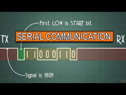
By modulating the TX pin state (Making it HIGH to send a 1, or LOW to send a 0), the sender is able to send a message over a connecting wire. The receiver reads the pin state at its RX pin to determine what was sent.
The serial communication protocol goes something like this…
Send a start bit (0 – LOW) “Hey, I’m getting ready to send a message!”
Followed by a set number of bits (often 8) “Here is my message…”
Optionally a parity bit “You sure you got this right?”
And finally a stop bit (1 – HIGH) “That’s all she wrote”
***Get the code, transcript, challenges, etc for this lesson on our website***
SERIAL READ VIDEO:
SERIAL BEGIN:
We designed this circuit board for beginners!
SHOP OUR FAVORITE STUFF! (affiliate links)
---------------------------------------------------
Get your Free Trial of Altium PCB design Software
We use Rev Captions for our subtitles
Arduino UNO R3:
Budget Arduino Kits:
Multimeter Options:
Helping Hands:
Soldering Stations:
AFFILIATES & REFERRALS
---------------------------------------------------
FOLLOW US ELSEWHERE
---------------------------------------------------
SO WHAT IS THIS U(S)ART THING?
Many microcontrollers come equipped with a simple way to communicate serially – using a USART. USART stands for Universal Synchronous/Asynchronous Receiver/Transmitter.
Wow – that’s one heck of a name! But let’s dive in – it actually way more reasonable than at first glance.
A USART is a piece of hardware. You’ll find it as either a stand-alone integrated circuit, or built right into a microcontroller.
An Arduino UNO for example uses an ATMEGA328P microcontroller which has a built-in USART.
This built-in USART (which uses the RX/TX pins on the Arduino) can send bytes of data serially to a different microcontroller on the Arduino UNO board, the ATMEGA16U2, which is used to handle the serial communication over USB.
USARTs allow us to take data in parallel from one device, convert it into a serial transmission, and then transform it back again into parallel data.
Now I want to draw attention to the Synchronous/Asynchronous part of USART for a moment – because that I think is most confusing. When serial communication protocols are synchronous (for example I2C, SPI) they use a clock signal for synchronizing the transmission from the sender to the receiver. The clock signal is what actively keeps the two in unison.
With an asynchronous protocol, there is no clock signal to synchronize the communication – which is why it requires a baud rate the receiver and the transmitter agree upon beforehand. We’ll be talking more about baud rate in just a moment.
The flavor of serial communication between these two USARTS is often referred to as TTL serial. TTL stands for Transistor-Transistor-Logic (We will not be diving into the details of TTL in this discussion).
It’s this TTL serial communication that we will use as a basis for our discussion of serial communication.
THE NITTY GRITTY OF TTL SERIAL COMMUNICATION
How does it work? Well it’s pretty cool.
Each USART has a TX and RX pin. The TX pin of the sending device is connected to the RX pin of the receiving device and vice versa.
By modulating the TX pin state (Making it HIGH to send a 1, or LOW to send a 0), the sender is able to send a message over a connecting wire. The receiver reads the pin state at its RX pin to determine what was sent.
The serial communication protocol goes something like this…
Send a start bit (0 – LOW) “Hey, I’m getting ready to send a message!”
Followed by a set number of bits (often 8) “Here is my message…”
Optionally a parity bit “You sure you got this right?”
And finally a stop bit (1 – HIGH) “That’s all she wrote”
 0:02:39
TTL Serial Communication Explained | Part 2
 0:09:47
TTL Serial Communication Protocol Explained | Part 3
 0:05:24
The inner workings of Serial Communication Explained | Part 1
 0:04:50
Serial Communication Basics
 0:11:58
PROTOCOLS: UART - I2C - SPI - Serial communications #001
 0:26:10
The RS-232 protocol
 0:04:35
Serial Ports Are STILL Around!
 0:07:30
Serial communication protocols - what are the differences?
 0:10:52
how does UART work??? (explained clearly)
 0:01:46
1-Minute Intro: USB 2.0 to TTL UART Converter Module RS232 CP2102
 0:05:42
What is RS232 and What is it Used for?
 0:16:51
Serial Communication with Arduino - The details!
 0:02:09
How USB to TTL Works ? | 3D Animated 🔥
 0:17:40
Hacker's Guide to UART Root Shells
 0:02:26
Serial Port Monitor - RS232 Logger software to analyze COM port
 0:00:15
TTL Serial Communication | RS-232 | Best Arduino Module | Best Arduino Module For Beginners #shorts
 0:00:08
TTL to RS232 to TTL Converter
 0:00:43
Reading RS232 Data from a weighing scale using Arduino UNO
 0:09:42
FTDI USB to Serial Adapter Demo
 0:40:29
What is RS485 serial communication? How to use RS-485 MODBUS to design Arduino point-point network.
 0:19:03
RS 232 Serial Communication Protocol
 0:01:41
Transmit data using UART in ESP32 | ESP32 -ESP32 | Serial communication
 0:07:54
Difference between RS 232 RS 422 and RS 485 communication
 0:00:07
RS232 to TTL Converter Module
Комментарии