filmov
tv
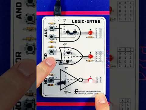
Diode Logic Gates - OR, NOR, AND, & NAND

Показать описание
This electronics video tutorial provides a basic introduction into logic gates using diodes, resistors, and LEDs. Examples include OR, NOR, AND, & NAND Diode Logic Gates.
How To Solve Diode Circuit Problems:
Clipper Circuits:
Clamper Circuits:
Half-Wave Rectifiers:
__________________________________
Full-Wave Rectifiers:
Full-Wave Bridge Rectifiers:
220V AC to 12V DC Converter:
Capacitor Voltage Booster Circuit:
Half Wave Voltage Doubler Circuit:
Full Wave Voltage Doubler Circuit:
__________________________________
Voltage Multiplier Circuit:
Light Emitting Diodes:
Power Dissipation In LEDs & Diodes:
Final Exams and Video Playlists:
Full-Length Videos and Worksheets:
___________________________________
Disclaimer: Some of the links associated with this video may generate affiliate commissions on my behalf. As an amazon associate, I earn from qualifying purchases that you may make through such affiliate links.
 0:22:10
Diode Logic Gates - OR, NOR, AND, & NAND
 0:03:59
L4 1 3Ideal Diode and Logic Gates
 0:05:59
Diode OR gate logic circuit explanation | Diode logic gate
 0:17:55
Diode Logic Gates || AND and OR logic gates || Example 4.2 || EDC 4.1.3(1)(Sedra)
 0:09:09
Logic Gates using Diode & Transistors | JEE Main Physics | Semiconductors | Eduniti | Mohit Sir
 0:04:36
Diode logic OR gate demonstration circuit by electronzap
 0:02:29
AND gate using diodes,Experiment
 0:16:33
TTL Logic: TTL NAND and NOR gates Explained
 0:00:06
Varactor diode #varactordiode #diode #electronics #electronicseducation #electronicsrd
 0:00:07
How to make Diode based AND Gate
 0:00:23
Logic Gates Learning Kit #2 - Transistor Demo
 0:15:14
Diode AND Gate & OR Gate || Exercise 4.4(e & f) ||EDC 4.1.3(2b)(Sedra)
 0:00:06
Logic Gate - XOR #shorts
 0:00:18
And Gates #electronics #circuit #electricalengineering #breadboard #Engineer #engineering #analog
 0:00:26
Diode Logic Gate Signal integrity test - 1n4148, BAW56, BAT54A
 0:00:07
Implementation of a INVERTER ('NOT' logic gate) using a bipolar transistor 2N2222
 0:07:10
Diode Logic Circuits
 0:09:04
AND Gate Using Diodes (Everything Explained!)
 0:02:39
Diode Logic Gates
 0:14:29
Diode AND Logic Gate using Ideal Model
 0:02:26
OR gate using diode, Experiment
 0:01:00
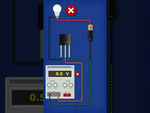
Transistors Explained - What is a transistor?
 0:07:43
Diode AND Gate logic circuit | Digital Electronics
 0:08:44
Diode Logic
Комментарии