filmov
tv
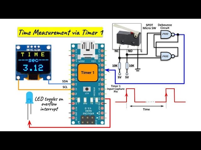
Time Measurement via Arduino Timer
Показать описание
ATmega328's Timer 1 is programmed to generate input capture & overflow interrupts to measure the time between two consecutives pulses input at Arduino's pin D8.
Link to code:
Contents:
0:00 Introduction
0:16 Block Diagram of Implemented System
1:28 Time Measurement via TIMER1
3:00 TIMER1 Registers
3:39 C++ Code
5:17 Demonstration
Link to code:
Contents:
0:00 Introduction
0:16 Block Diagram of Implemented System
1:28 Time Measurement via TIMER1
3:00 TIMER1 Registers
3:39 C++ Code
5:17 Demonstration
 0:05:52
Time Measurement via Arduino Timer
 0:06:09
Arduino Time Measurement
 0:04:51
Time Measurement via Arduino Timer (part 2)
 0:04:17
Frequency Measurement via Arduino Timer
 0:00:14
Arduino Sport Timing System
 0:16:13
Timer Interrupt ISR + Examples | Arduino101 | Set Registers & Modes
 0:09:19
Electronic Basics #30: Microcontroller (Arduino) Timers
 0:09:37
Tinkercad + Arduino Lesson 13: Timers Part 4 (Measure Pulse Duration)
 0:06:34
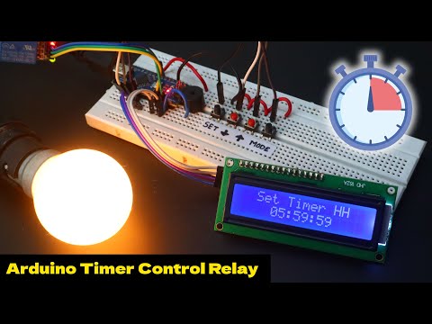
Arduino Timer Control Relay Devices
 0:08:19
Arduino Timer Tutorial - What are timers & how to use them in Arduino
 0:48:17
Understanding Arduino Interrupts | Hardware, Pin Change & Timer Interrupts
 0:00:16
Amazing arduino project | Check description to get free money.
 0:06:27
Frequency Counter using Arduino Timers
 0:04:54
Input Capture Interrupt in Arduino
 0:05:22
ARDUINO TIMER CIRCUIT WITH I2C LCD| WITH CODE AND DIAGRAM sk raghav ix
 0:09:21
Arduino Based Reaction Timer - Improve Your Reaction Time
 0:05:36
Arduino Timer 1 Interrupts via External Clock
 0:00:22
What engineering students actually do in labs 💀 #electronics #arduino #engineering
![[Embedded] How to](https://i.ytimg.com/vi/wnCeowBU2V4/hqdefault.jpg) 0:05:38
0:05:38
[Embedded] How to use TimerOne library in Arduino IDE
 0:04:21
Arduino Prototyping Techniques #87: Measuring Time (Millis)
 0:09:36
Timer Compare Match Interrupt in Arduino
 0:17:22
Level Up Your Arduino Code: Timer Interrupts
 0:00:34
Arduino project: Measure reaction time
 0:12:34
Countdown Creation: Arduino Timer with OLED Display using millis() function
Комментарии