filmov
tv
How to Read an Oil & Gas P&ID with Control Valve Symbols Explained (ANSI/ISA 5.1)

Показать описание
=============================
0:00 Introduction
0:21 P&ID vs PFD
1:35 P&ID Tag Numbers and Abbreviations
3:20 P&ID Instrument Location
4:03 Shared Display / Shared Control
4:49 P&ID Line Types
5:10 P&ID Piping Symbols
5:27 P&ID Control Valve Symbols and Actuator Symbols
5:40 P&ID Pump, Tank and Equipment Symbols
=============================
---
In many industries, engineers will create a blueprint for equipment and control layout, called a Piping and Instrumentation Diagram, or P&ID. In this video, we’ll walk through codes and symbols specifically for oil and gas production equipment so you can understand and read a P&ID in the industry.
Not all P&ID elements are standardized, but the instrumentation symbols follow a standard set by the International Society of Automation (ISA). The ANSI/ISA’s S5.1 standards are what this guide will be using to communicate consistently.
---
 0:01:22
A Dipstick Trick for Reading Clean Engine Oil Levels #13
 0:06:35
How to Check Your Oil Level & Read Your Dipstick
 0:00:34
How to check dipstick oil level
 0:00:18
#6 What do the marks on my OIL dipstick mean?
 0:07:46
How to Check Your Engine Oil Level & Read an Oil Dipstick
 0:00:54
How to Check the Oil in your Car
 0:05:15
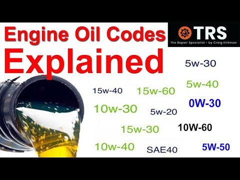
Engine Oil Codes Explained, SAE (Society of Automotive Engineers) numbers (by Craig Kirkman)
 0:01:41
How to read an oil dipstick: A tutorial
 0:01:18
How to Check Your Oil Level & Read Your Dipstick🙃 #themobilemechanic757
 0:04:05
Quick Tips - How to Read an Oil Analysis Report
 0:01:07
how to READ the dipstick in your car
 0:19:53
HOW TO READ AN OIL REPORT
 0:00:52
Can't read oil Dipstick - FIX
 0:03:09
How To Read Oil Dipstick With 2 Holes (Easy-To-Follow Guide)
 0:10:45
QUICK TIP: HOW TO UNDERSTAND AND READ YOUR CARS OIL DIPSTICK SO YOU GET THE PROPER LEVEL OF FLUID!
 0:00:58
How to read oil on a hard to read dipstick. #mechanic #diy #lifehacks
 0:00:30
How to read the oil dipstick on a Mini Cooper
 0:01:01
How To: Check Your Oil and Read Your Dipstick
 0:00:28
👉 Tip 2️⃣ Reading your oil dipstick 👈 When was the last time you checked your oil level? 🤔...
 0:02:10
PRO TIPS #5: How To Read Engine Oil Dipstick
 0:06:21
Learn Oil Analysis - How to read an oil sample report
 0:01:29
How to read oil dipstick with 2 holes?
 0:04:44
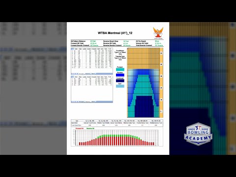
How to Read an Oil Pattern Sheet: Understanding Bowling Lane Oil Patterns
 0:01:47
How to read a oil dipstick . Pt 1
Комментарии