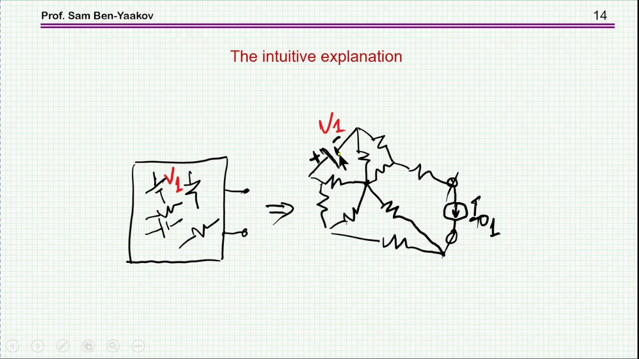
A recent extension to Thevenin’s theorem and solution to ‘equivalent circuit riddle’

preview_player
Показать описание

Рекомендации по теме
Комментарии
Автор

Wow, again a videolesson in which there was even more interesting things to learn than only the things from the title. And thanks to the riddle i could hardly wait much longer. Really a joy to learn this way!

robson
Автор

Wow I can enjoy this this weekend! Thank you Prof. Sam

justinn
Автор

Thank you very much for this interesting video which sparked my curiosity about the general case and has lead to many hours of fun experimentation. I now believe that, indeed, simply adding a current source between the two output terminals of the proposed equivalent circuit suffices to turn it into a universal equivalent circuit.
To explain why I think this is true, I will adopt your approach of attaching a current source with value I_o to the two terminals of the original network. I will also denote the values of the elements of the Thévenin circuit equivalent to the network by V_t and R_t.
It is probably well known that for each resistor in the network, the current through the resistor is a linear polynomial of the load current I_o. Therefore, the power dissipated by a particular resistor in the network is a quadratic polynomial in I_o taking only nonnegative values. Consequently, the power dissipated by all the resistors in the network combined is also a quadratic polynomial in I_o taking only nonnegative values. Elementary algebra shows that such a polynomial is always of the form (I_o - I_x)^2 * R + P_x. Here, I_x is the load current at which the power consumption in the resistors of the network is minimal, R >= 0 is a resistance, and P_x >= 0 is the minimum power consumed by the resistors of the network.
Now I need to state a conjecture which I believe to be true but of which I was unfortunately unable to obtain a formal proof:
(*) The resistance R in the above polynomial is indeed equal to the output impedance R_t of the network.
Professor Barbi shows that (*) is true when no current sources are present and that the current of minimum power consumption I_x is zero in this case. I would be willing to bet that (*) also holds true for networks without voltage sources and that then the current of minimum power consumption I_x is simply the short circuit current of the network. (This is consistent with the example at the end of the video where the power consumption at short circuit is zero and hence obviously minimal.) I tried a fairly large and fairly random network and (*) was true for this as well, so I am fairly confident that it in fact holds in the general case.
Now if the network satisfies (*), then there exists an equivalent network consisting of the circuit shown at 5:00 in parallel with a current source with value I_x. The value of the voltage source in the equivalent circuit has to be adjusted from V_t to V_x := V_t - I_x * R_t and the value of the resistor R_x has to be set to V_x^2 / P_x. A quick computation shows that the output voltage of this modified circuit is indeed given by V_o = V_x - (I_o - I_x) * R_t = V_t - I_x * R_t - I_o * R_t + I_x * R_t = V_t - I_o * R_t, proving the electrical equivalence, and the power dissipated in the resistors R_t and R_x amounts to (I_o - I_x)^2 * R_t + V_x^2 / R_x = (I_o - I_x)^2 * R_t + P_x, confirming, in view of (*), the power equivalence.
Universal equivalent circuits can also be constructed by connecting a Thévenin circuit and a Norton circuit either in parallel or in series, but the computation of the element values is more cumbersome.
Sadly, apart from failing to prove (*), I was also unable to find a nice and simple way of computing I_x and P_x in the general case.

Edit: While I was preparing this comment, the user EpiScintilate proposed the same equivalent circuit motivated by a superposition consideration.

julianahrens
Автор

One never stops learning (that much we all know) but this has been a big surprise for me. I never imagined after all this time spent with electronics that I'd learn that Norton and Thevenin were not fully equivalent! I guess in the haste of learning more and more and more, sometimes the underlying assumptions that the whole edifice was based on in the first place are forgotten. That can prove to be a pricey mistake to make the further one goes. I'll be on the look-out for a fully equivalent version of Norton and Thevenin circuits now.

Stelios.Posantzis
Автор

That's quite interesting... Thank you

dhanushavvari
Автор

Thank you so much, Prof. Sam, for this video. What about modelling the constant loss as a resistor in series with the current source in the example presented towards the end?

aasheeshc
Автор

One idea is to separate the Voltage and Current equivs
as far as power is concerned.
Based on superposition, separate the contributions of
Voltage and Current sources in the network.
RT = Thevenin/Norton equiv.
VT = Thevenin equiv. of voltage sources. (o/p open ckt V)
IN = Norton equiv. of current sources. (o/p short ckt I)
(can also use open ckt voltage for current sources.)
An equivalent ckt for the superposition is:
VT in series with Rt feeding
then connect IN across the output terminals.
IN will contribute no-load power dissipation which decreases with
load. An additional load across VT (as per Barbi) increases the
no-load power dissipation to match the actual ckt.
With this construction it seems the short-circuit power dissipation
also agrees but I've only check a few simple cases.

EpiScintilate
Автор

can we place a diode at the output and check both the circuits ?

sreejithraveendran