filmov
tv
Transistor Transistor Logic (TTL): TTL NAND Gate Circuit and Working

Показать описание
Transistor Transistor Logic (TTL) is covered by the following Timestamps:
0:00 - Digital Electronics Lecture Series.
0:20 - Transistor Transistor Logic TTL Classifications
1:02 - Transistor Transistor Logic TTL Basics
2:25 - TTL NAND Gate Circuit
5:37 - TTL NAND Gate Working
9:39 - TTL Components Details
Following points are covered in this video:
1. Transistor Transistor Logic TTL
2. Transistor Transistor Logic TTL Classifications
3. Transistor Transistor Logic TTL Basics
4. TTL NAND Gate Circuit
5. TTL NAND Gate Working
6. TTL Components Details
Chapter-wise detailed Syllabus of the Digital Electronics Course is as follows:
Binary, hex, octal, decimal, BCD, integer, and floating-point- numbers, code conversion etc.
Laws of Boolean Algebra, SOP, POS, Dual and Self Dual of Boolean equation, Minterms, Maxterms, Quine McCluskey Technique, etc.
AND, OR, NOT, XOR, XNOR, NAND, NOR Gates and Circuit implementation using universal gates.
Minimization of functions using Boolean identities and many other circuits like Multiplexer, Demultiplexer, Adder, Subtractor, Decoder, Encoder, Carry look ahead adder, Even Parity Generator and Odd Parity Generator, Priority Encoder, etc.
IK-map basics, Implicants, Prime Implicants and Essential Prime, 3,4,5 and 6 variable K Map, Quine McCluskey Minimization Technique
DTL, RTL, TTL, CMOS, Boolean Function Implementations, Stick Diagram of Boolean Function, CMOS Transmission Gate, etc.
Clock and Triggering by clock in Sequential circuit, Latch, Flip Flops, Master Slave Flip Flop, Counters, Shift Registers, State Machines, Mealy State Machine and Moore State Machine
ROM, RAM, PLA, PAL, Digital to Analog Converter and Analog to Digital Converter
Practical's on Logic gates, Adder, Code conversion, Comparator, Flip flop, Counter, Register, etc.
Engineering Funda channel is all about Engineering and Technology. Here this video is a part of Digital Electronics and Logic Families.
#DigitalElectronics #DigitalLogicDesign #TransistorTransistorLogic @EngineeringFunda
 0:12:25
Transistor Transistor Logic (TTL): TTL NAND Gate Circuit and Working
 0:08:34
Transistor Transistor Logic
 0:19:17
Transistor Logic Gates - NAND, AND, OR, NOR
 0:09:58
Transistor-Transistor Logic (TTL)
 0:01:56
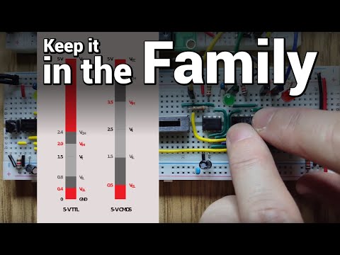
CMOS vs TTL: What are Logic Families?
 0:00:50
Transistor Transistor Logic (TTL)
 0:10:30
Modified Transistor Transistor Logic (TTL) - Digital Circuits and Logic Design
 0:08:32
Transistor - Transistor Logic (TTL) NAND Gate
 0:09:49
Comparison of logic families in digital electronics
 0:13:13
Transistor Transistor Logic (TTL) - Digital Circuits and Logic Design
 0:16:07
Experment#6: Transistor-Transistor Logic (TTL) Gates
 0:15:19
TTL NAND Gate with Totem Pole Output: Circuit and Working
 0:11:13
Transistor Transistor Logic (TTL) | TTL as NAND Gate | Digital Circuits | Logic Families
 2:19:58
Transistor Transistor Logic (TTL)
 0:11:34
TTL(Transistor-Transistor Logic)Circuit|Logic Families|Digital Electronics
 0:05:24
TTL (TRANSISTOR-TRANSISTOR logic)
 0:03:50
A9 2 Transistor-Transistor-Logik, TTL
 0:01:46
TTL logic
 0:22:05
Module 5 || Transistor Transistor Logic (TTL)
 0:13:08
Electronics 201: Transistor Transistor Logic
 0:13:10
Transistor Transistor Logic Family 1 - Digital Logic and Logic Families - Industrial Electronics
 0:26:33
Integrated Circuits Technologies: TTL Circuits
 0:13:39
7. TTL (Transistor -Transistor Logic) Circuit | Digital Logic Families | TECH GURUKUL By Dinesh Arya
 0:11:29
TTL Tristate Logic Explained: Circuit and Working
Комментарии