filmov
tv
How to make a TA2111 FM Radio Receiver schematic circuit diagram

Показать описание
Here is a schematic to go with the FM Receiver!
Special thanks to Peter Vis for his help on this build!
The TA2111 is a bit trickier than some other radio chips as it includes switching circuits for stereo, soft mute and AM as well as a shared IF pin, and separate output pins. Each of these bypass circuits can turn off the FM radio you're trying to build. When you begin, you can take your output directly from the Detector pin 18, just to see if your tank circuits are resonating. Afterwards, when you finish the LP1 & LP2 networks you can take the output from the LOut & ROut pins. If you don't even hear static when your attempting this build... check your connections and refer to the datasheet.
I drew the diagram as FM mono for simplicity. For stereo, simply duplicate the Output Network and separate pins 14 and 13, then connect pin 15 directly to the positive rail. You can use a simple switch to connect pin 15 to positive, thus bypassing the 104 cap and 3.3k resistor when the switch is closed or as mono when the switch is open
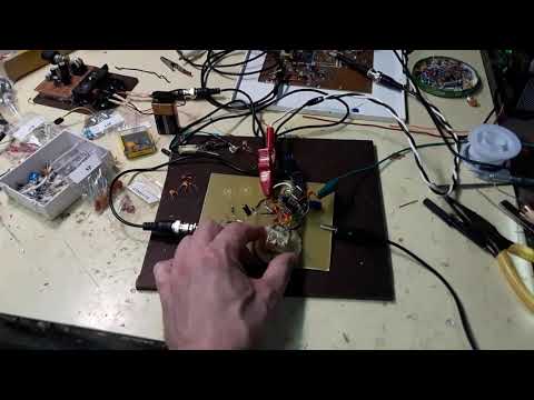
For the build in the demonstration video, I used a copper clad board and super-glued the chip directly to the board upside down, dead bug style. The main board is ground. The positive rail runs through the red glued-on pads and the two jumper wires.
Be sure the wire from pin 21 to the oscillator tank does not cross over or run exactly parallel with any positive wire. The oscillator tank and the chip should be surrounded by the ground plane.
I also cut separate pads for each pin of the variable capacitor to isolate it from the board. Take special note that the variable capacitor tuner is not connected to ground. The VC stator (center pin) connects to the positive rail through the "RF VCC" (pin 22).
For the coils, I used 23awg magnet wire with a 5mm diameter. Depending on the VC you're using, you will have to experiment with different coils and trimming and padding caps to get the tank circuits working.
The 4pF cap connecting pins 21 & 19 is a critical component. A different value will not work.
The IF network functions best using ceramic resonators / filters. Note the positions of the 3 and 2 pin filters respectively. I also experimented with a 3 pin crystal resonator of the same value, but it did not work as well as the ceramic. Crystals tend to have a very narrow bandwidth.
The ceramic BP filter connected to the antenna is not crucial. You can pull one from an old radio, as I did, or just connect pin 1 to a telescopic antenna with a 22pF cap and a 75 Ohm resistor. You can also make a simple band pass tank circuit with a 7 turn coil and and trimmer cap.
Special thanks to Peter Vis for his help on this build!
The TA2111 is a bit trickier than some other radio chips as it includes switching circuits for stereo, soft mute and AM as well as a shared IF pin, and separate output pins. Each of these bypass circuits can turn off the FM radio you're trying to build. When you begin, you can take your output directly from the Detector pin 18, just to see if your tank circuits are resonating. Afterwards, when you finish the LP1 & LP2 networks you can take the output from the LOut & ROut pins. If you don't even hear static when your attempting this build... check your connections and refer to the datasheet.
I drew the diagram as FM mono for simplicity. For stereo, simply duplicate the Output Network and separate pins 14 and 13, then connect pin 15 directly to the positive rail. You can use a simple switch to connect pin 15 to positive, thus bypassing the 104 cap and 3.3k resistor when the switch is closed or as mono when the switch is open
For the build in the demonstration video, I used a copper clad board and super-glued the chip directly to the board upside down, dead bug style. The main board is ground. The positive rail runs through the red glued-on pads and the two jumper wires.
Be sure the wire from pin 21 to the oscillator tank does not cross over or run exactly parallel with any positive wire. The oscillator tank and the chip should be surrounded by the ground plane.
I also cut separate pads for each pin of the variable capacitor to isolate it from the board. Take special note that the variable capacitor tuner is not connected to ground. The VC stator (center pin) connects to the positive rail through the "RF VCC" (pin 22).
For the coils, I used 23awg magnet wire with a 5mm diameter. Depending on the VC you're using, you will have to experiment with different coils and trimming and padding caps to get the tank circuits working.
The 4pF cap connecting pins 21 & 19 is a critical component. A different value will not work.
The IF network functions best using ceramic resonators / filters. Note the positions of the 3 and 2 pin filters respectively. I also experimented with a 3 pin crystal resonator of the same value, but it did not work as well as the ceramic. Crystals tend to have a very narrow bandwidth.
The ceramic BP filter connected to the antenna is not crucial. You can pull one from an old radio, as I did, or just connect pin 1 to a telescopic antenna with a 22pF cap and a 75 Ohm resistor. You can also make a simple band pass tank circuit with a 7 turn coil and and trimmer cap.
 0:00:32
How to make a TA2111 FM Radio Receiver schematic circuit diagram
 0:00:31
TA2111 FM Receiver 9
 0:00:41
TA2111 AM Receiver
 0:00:36
TA2111 FM Receiver 7
 0:01:10
TA2111 FM Receiver 5
 0:00:31
TA2111 FM experiment 1
 0:00:46
TA2111 FM Receiver 6
 0:00:36
TA2111 FM Receiver 8
 0:00:36
TA2111 FM experiment 2
 0:00:30
TA2111
 0:00:31
TA2111 FM Experiment 4
 0:01:48
TA2111 FM Radio Receiver 10
 0:00:46
TA2111 FM experiment 3
 0:06:07
How to make World's Simple Musical Light | Audio Level Light
 0:18:58
DERB - AM Superhet Receiver - Wiring bigins
 0:00:06
AM redio reciever circuit
 0:00:31
How to Make a Regen FM Regenerative Receiver radio schematic
 0:09:43
Homemade FM Radio Circuit: Enjoy Your Favorite Stations for Free!
 0:03:01
How to make the most powerful antenna on earth for terrestrial broadcasting || RF ANTENNA DESIGNS
 0:02:27
Building an FM Radio
 0:01:58
USB Powered FM transmitter (demo with circuit diagram)
 0:10:16
How to make the smallest Radio Receiver at home (Part 3 of 4)
 0:00:18
simple FM radio Reciver circuit diagram using 2 npn transistors and audio ic lm386
 0:21:05
Let's make an FM Radio
Комментарии