filmov
tv
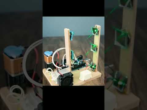
Another Arduino project - Your Arduino Balancing Robot (YABR) - Part 1

Показать описание
In this video I build an Arduino balancing robot. The code that I use is self-written and is available from my website. A detailed built tutorial, drawings for the frame and electrical schematics can also be downloaded from my website:
If you have any questions please check the Q&A page first:
The code is explained in detail in the following videos:
If you have any questions please check the Q&A page first:
The code is explained in detail in the following videos:
 0:11:49
Another Arduino project - Your Arduino Balancing Robot (YABR) - Part 1
 0:00:21
AI is getting too smart 💀 #electronics #arduino #engineering
 0:01:01
Arduino Explained in 60 Seconds! #arduino #electronics #STEM
 0:00:51
Your house guests will definitely love this 💀 #electronics #arduino #engineering
 0:00:17
When The Quiet Kid Does Your Homework 💀 #electronics #arduino #engineering
 0:00:18
When Your Crush Knows Morse Code 💀 #electronics #arduino #engineering
 0:00:30
Amazing Experiment with Arduino Nano | Flappy Bird Game #diyprojects #arduino #3dprinting #tech
 0:00:16
Amazing Arduino project #3dprinting #machine #3dprinted #toys #3dprint
 0:00:21
10,000ft & MAKING electronics! Maker on-the-move: build wherever you are.
 0:00:08
Mind-boggling arduino UNO project. You need to do it yourself! #arduino #electronics
 0:00:23
3 UNREAL Beginner Arduino Projects - Easier than they look!
 0:01:05
Air Defense System- DIY Arduino Project - The X Lab
 0:00:16
Top 5 Arduino Projects #arduino #arduinoprojects #arduinorobot #lightdetector
 0:00:16
Arduino project how to make a laser electronic alarm, an amazing invention DIY
 0:00:15
Top Five Arduino Projects #diy #arduino #arduinoprojects #experiment #eazytronic
 0:00:24
EASY project to PRANK your roommate! #engineering #electronics #arduino
 0:00:13
Learn Motor Control with Arduino UNO R3 | Mini Car Project #arduino
 0:00:12
Smart Dustbin DIY #smartgadgets #smartdustbin #smarthouse #electrocse
 0:06:50
Arduino - How to Split a Program Into Different Files
 0:00:56
Mo-Chan & EMO - First Met 🥰 Make an Arduino Robot Ep.1 #emopet #robot #arduino
 0:00:19
Top Five Arduino Projects #arduinoprojects #eazytronic #arduinouno #arduinouno #experiment
 0:00:11
LED Matrix - Arduino Project for Beginners #arduino #engineering #diy
 0:00:19
Top 5 Arduino projects #shorts
 0:00:43
Arduino?ESP32?STM32?Raspberry Pi?Or Jetson Nano?#arduino #esp32 #stm32 #raspberrypi
Комментарии