filmov
tv
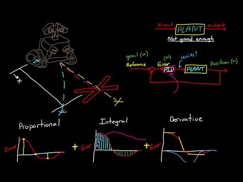
PID Theory and Practice Part 3, P,I,PI Control of Speed

Показать описание
Overview of PID controllers starting with basic definitions through using PI / PD controllers for controlling a (simulated) DC motor
Part 1
Definitions, basic terms
Part 2
Simple DC motor model
Part 3
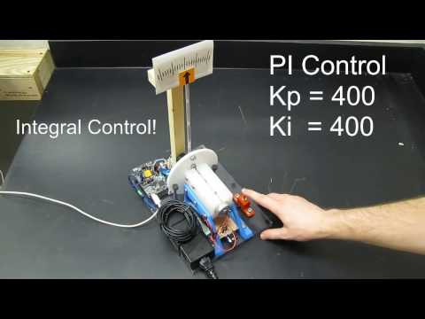
P, I, and PI control of motor velocity
Part 4
Practical considerations
Simple tuning rules
Part 5
PI, PD, and PID control of motor position
Psuedo Code for a PID controller - Typically only the P and I parts or P and D parts would be used.
Const F32 P_Gain = 1; // Gain for proportional controller
Const F32 I_Gain = .1; // Gain for integral controller
Const F32 D_Gain = .01 // Gain for derivative controller
Const F32 Filter_Const = .25 // Filter constant for filtering input to derivative controller
// minimum value = 0, maximum value = 1
F32 P_Control; // output of proportional controller
F32 I_Control; // output of integral controller
F32 D_Control; // output of integral controller
F32 Filter_Out; // output of filter
F32 Filter_Out_Prev // previous output of thefilter - use to get delta change
Const F32 Target_Value = 100; // target set point for controller
F32 Measured_Value; // measured plant output
F32 Error_Value; // difference between desired and measured plant output.
F32 PID_Out; // final controller output value
F32 Loop_Time // time for one control loop - could be a constant or a measured value
Measured_Value = input(); // get A/D reading -- convert units if necessary
Error_Value = Target_Value -- Measured_Value;
P_Control = P_Gain * Error_Value;
I_Control = I_Control + I_Gain * Error_Value * Loop_Time; // integrate error * gain*delta time
// If you leave out the loop time, you can adjust the gain value to somewhat compensate
Filter_Out_Prev = Filter_Out; // save previous value
Filter_Out = Filter_Const*Error_Value + (1-Filter_Constant)* Filter_Out;
// take a portion of the new input and a portion of the old value to average out over several samples
// simulate a first order exponential filter.
D_Control = D_Gain * (Filter_Out - Filter_Out_Previous) / Loop_Time; // derivative output based on filtered value
PID_Out = P_Control + I_Control + D_Control; // Final output
Part 1
Definitions, basic terms
Part 2
Simple DC motor model
Part 3
P, I, and PI control of motor velocity
Part 4
Practical considerations
Simple tuning rules
Part 5
PI, PD, and PID control of motor position
Psuedo Code for a PID controller - Typically only the P and I parts or P and D parts would be used.
Const F32 P_Gain = 1; // Gain for proportional controller
Const F32 I_Gain = .1; // Gain for integral controller
Const F32 D_Gain = .01 // Gain for derivative controller
Const F32 Filter_Const = .25 // Filter constant for filtering input to derivative controller
// minimum value = 0, maximum value = 1
F32 P_Control; // output of proportional controller
F32 I_Control; // output of integral controller
F32 D_Control; // output of integral controller
F32 Filter_Out; // output of filter
F32 Filter_Out_Prev // previous output of thefilter - use to get delta change
Const F32 Target_Value = 100; // target set point for controller
F32 Measured_Value; // measured plant output
F32 Error_Value; // difference between desired and measured plant output.
F32 PID_Out; // final controller output value
F32 Loop_Time // time for one control loop - could be a constant or a measured value
Measured_Value = input(); // get A/D reading -- convert units if necessary
Error_Value = Target_Value -- Measured_Value;
P_Control = P_Gain * Error_Value;
I_Control = I_Control + I_Gain * Error_Value * Loop_Time; // integrate error * gain*delta time
// If you leave out the loop time, you can adjust the gain value to somewhat compensate
Filter_Out_Prev = Filter_Out; // save previous value
Filter_Out = Filter_Const*Error_Value + (1-Filter_Constant)* Filter_Out;
// take a portion of the new input and a portion of the old value to average out over several samples
// simulate a first order exponential filter.
D_Control = D_Gain * (Filter_Out - Filter_Out_Previous) / Loop_Time; // derivative output based on filtered value
PID_Out = P_Control + I_Control + D_Control; // Final output
 0:11:51
PID Theory and Practice Part 3, P,I,PI Control of Speed
 0:12:19
PID Theory And Practice Part 5, PD control of position
 0:13:15
PID Theory and Practice Part 4, Practical Considerations, Tuning
 0:11:41
PID Control Theory And Practice Part 2, Simple DC Motor Model
 0:13:28
(Proportional -- Integral -- Derivative) PID Control Theory and Practice Part 1, Definitions
 0:07:44
PID Control - A brief introduction
 0:09:59
PID Theory and Robotics Explained
 0:11:42
What Is PID Control? | Understanding PID Control, Part 1
 0:06:25
PID Loop Tuning Explained - Part 1 - Proportional Only
 0:01:00
PID Control Lab - PID tuning in one minute (PIDlab.com)
 0:13:10
Simple Examples of PID Control
 0:15:03
PID Control – Closing the Loop
 0:24:56
Deep dive into the PID controller D-Term component
 0:02:58
Hardware Demo of a Digital PID Controller
 0:00:09
Control-Lab-in-a-Box (CLB): DC Motor Proportional and Integral (PI) Speed Control
 0:26:11
Introduction to PID Control
 0:01:01
P, PI, PID Controllers
 0:00:13
Position Control using PID controller
 0:04:22
PID Control
 0:34:06
PID Control Simplified
 0:07:36
Control Systems - PID calculations
 0:12:14
PID Control Fundamentals (Lectures on Control Systems)
 0:22:19
What is a PID Controller? | DigiKey
 0:33:01
Designing a PID Controller Using the Ziegler-Nichols Method
Комментарии