filmov
tv
STM32CubeIDE Course for beginners, stm32f103c8t6, STM32 CubeIDE #stm32cubeIDE
Показать описание
STM32 CubeIDE Course for beginners
Welcome to my STM32 CubeIDE Course specifically designed for Beginners. In this course, we will take a step-by-step approach to ensure that you gain a solid understanding of how to use CudeIDE for programming the STM32 Microcontroller.
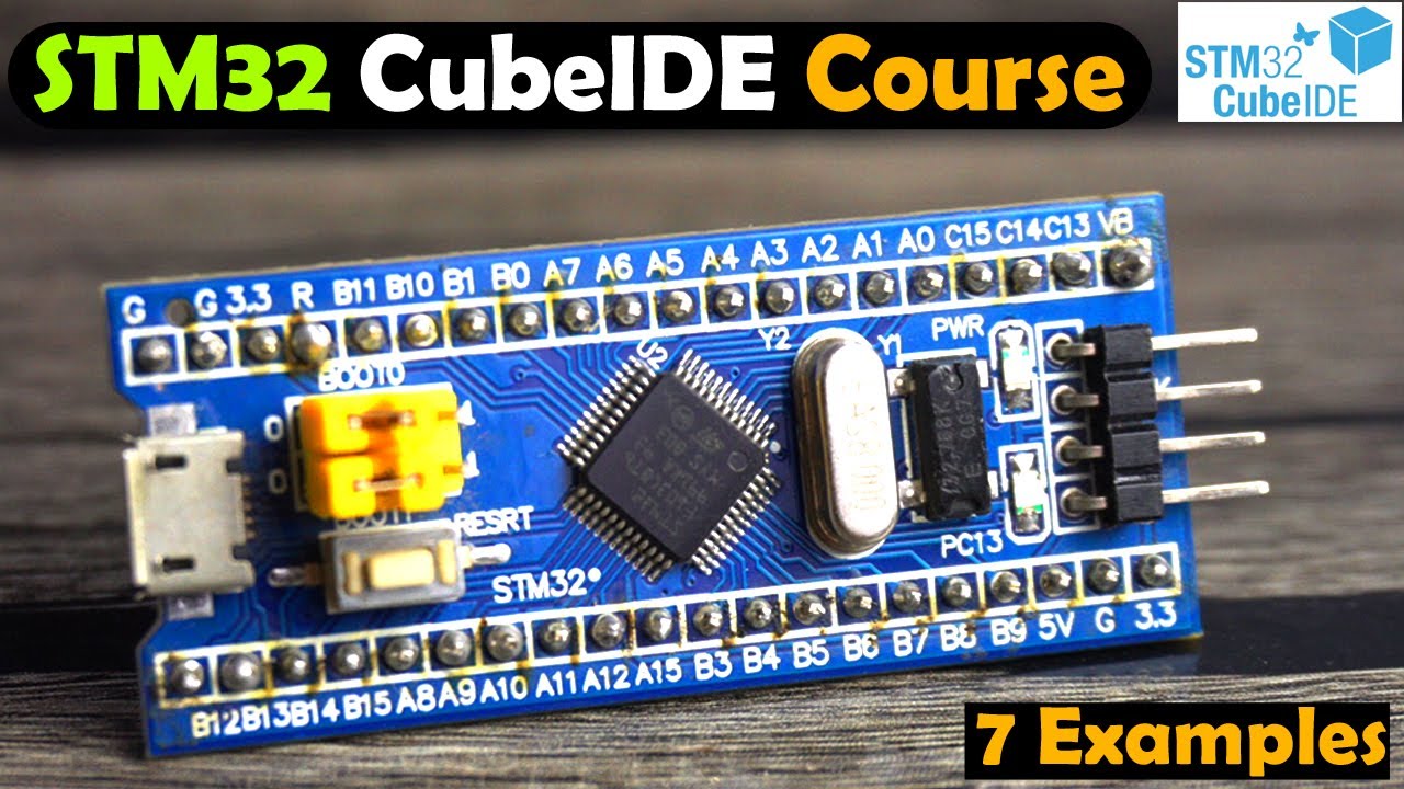
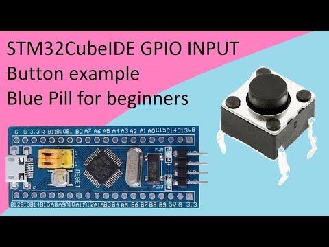
Throughout this course, I will be using the most popular STM32F103C8T6 microcontroller board which is also known as Blue Pill, and for uploading the programming I will use the ST-Link V2.
Altium Designer: For Schematic and PCB designing
Altium 365:
Octopart, components search engine:
Download codes and circuit diagrams:
Related Videos:
STM32 with Arduino IDE, Bootloader
STM32 and DHT11, Arduino IDE
STM32 and LoRa, Arduino IDE
STM32 LoRa and ESP8266 Gateway
5V Power Supply for STM32
Support me on Patreon and get access to hundreds of projects:
Subscribe to my New YouTube Channel, if you want to watch my videos in Hindi/Urdu
Project Description:
********************
Since, this course is for the absolute beginners, so, I will try my level best to explain each and every detail including,
1. STM32 Blue Pill Board Technical specifications and Pinout.
2. What is CubeIDE? and
3. How to Download and Install STM32CudeIDE.
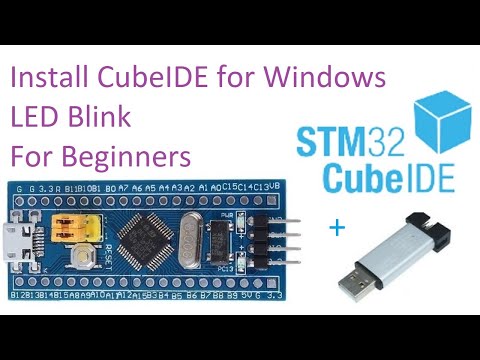
After covering the most basic things then I will practically show you, how to use the most commonly used electronics components with the STM32. Since this course is for the beginners, so first I will start with the easiest example which is controlling the STM32 onboard LED.
Then in the 2nd example, I will show you how to connect and control external LEDs. These LED blinking examples will help you in understanding; how to turn ON and turn OFF any GPIO pins on the STM32.
In 3rd example, I will show you, how to read a digital input on any GPIO pin of the STM32; for this, I will use a Pushbutton. We will be reading and controlling both at the same time. The STM32 board will sense the button click and then accordingly will turn ON or turn OFF the LED.
In 4th example, I will show you how to interface an I2C supported 16x2 LCD. This is one of the most commonly used LCDs; We will simply print the Hello World text message on the LCD module.
In the 5th example, I will show you how to use an analog sensor with the STM32 and display its value on the I2C supported 16x2 LCD. For demonstration purposes, I will be using a Potentiometer as the analog sensor. After understanding this example then you would be able to use all types of Analog sensors, like for example, LDRs, Flex Sensors, Force Sensors, etc. There is a long list of the Analog Sensors.
In the 6th example, I will show you how to connect an I2C Supported Oled display module with the STM32. I will write a very basic program to print some text on the Oled display module. This is really an important example because in most of the projects you will need an Oled display module to print text messages and sensor values.
In 7th example, I will explain how to make a simple distance measurement system using the most popular HC-SR04 Ultrasonic Sensor. We will simply measure the distance and then print it on the i2c supported SSD1306 Oled display module.
********************
Amazon Purchase links:
*****************
STM32 Blue Pill Board
SSD1306 Oled Display Module
HC-SR04 Ultrasonic Sensor
Push Button
I2C supported 16×2 LCD
Other must-have Tools and Components:
Arduino Uno, Nano, Mega, Micro "All types of Arduino Boards":
Top Arduino Sensors:
Top Oscilloscopes
3D printers:
CNC Machines:
DISCLAIMER: This video and description contain affiliate links, which means that if you click on one of the product links, I will receive a small commission. This helps support the channel and allows me to continue to make videos like this. Thank you for your support!
****************
For more Projects and tutorials visit my Websites
Electronic Clinic:
Programming Digest:
Follow me on Instagram:
Follow my Facebook Page Electronic Clinic:
Follow my Facebook Group, Arduino Projects:
Email:
#stm32cubeide #stm32 #altiumdesigner
Welcome to my STM32 CubeIDE Course specifically designed for Beginners. In this course, we will take a step-by-step approach to ensure that you gain a solid understanding of how to use CudeIDE for programming the STM32 Microcontroller.
Throughout this course, I will be using the most popular STM32F103C8T6 microcontroller board which is also known as Blue Pill, and for uploading the programming I will use the ST-Link V2.
Altium Designer: For Schematic and PCB designing
Altium 365:
Octopart, components search engine:
Download codes and circuit diagrams:
Related Videos:
STM32 with Arduino IDE, Bootloader
STM32 and DHT11, Arduino IDE
STM32 and LoRa, Arduino IDE
STM32 LoRa and ESP8266 Gateway
5V Power Supply for STM32
Support me on Patreon and get access to hundreds of projects:
Subscribe to my New YouTube Channel, if you want to watch my videos in Hindi/Urdu
Project Description:
********************
Since, this course is for the absolute beginners, so, I will try my level best to explain each and every detail including,
1. STM32 Blue Pill Board Technical specifications and Pinout.
2. What is CubeIDE? and
3. How to Download and Install STM32CudeIDE.
After covering the most basic things then I will practically show you, how to use the most commonly used electronics components with the STM32. Since this course is for the beginners, so first I will start with the easiest example which is controlling the STM32 onboard LED.
Then in the 2nd example, I will show you how to connect and control external LEDs. These LED blinking examples will help you in understanding; how to turn ON and turn OFF any GPIO pins on the STM32.
In 3rd example, I will show you, how to read a digital input on any GPIO pin of the STM32; for this, I will use a Pushbutton. We will be reading and controlling both at the same time. The STM32 board will sense the button click and then accordingly will turn ON or turn OFF the LED.
In 4th example, I will show you how to interface an I2C supported 16x2 LCD. This is one of the most commonly used LCDs; We will simply print the Hello World text message on the LCD module.
In the 5th example, I will show you how to use an analog sensor with the STM32 and display its value on the I2C supported 16x2 LCD. For demonstration purposes, I will be using a Potentiometer as the analog sensor. After understanding this example then you would be able to use all types of Analog sensors, like for example, LDRs, Flex Sensors, Force Sensors, etc. There is a long list of the Analog Sensors.
In the 6th example, I will show you how to connect an I2C Supported Oled display module with the STM32. I will write a very basic program to print some text on the Oled display module. This is really an important example because in most of the projects you will need an Oled display module to print text messages and sensor values.
In 7th example, I will explain how to make a simple distance measurement system using the most popular HC-SR04 Ultrasonic Sensor. We will simply measure the distance and then print it on the i2c supported SSD1306 Oled display module.
********************
Amazon Purchase links:
*****************
STM32 Blue Pill Board
SSD1306 Oled Display Module
HC-SR04 Ultrasonic Sensor
Push Button
I2C supported 16×2 LCD
Other must-have Tools and Components:
Arduino Uno, Nano, Mega, Micro "All types of Arduino Boards":
Top Arduino Sensors:
Top Oscilloscopes
3D printers:
CNC Machines:
DISCLAIMER: This video and description contain affiliate links, which means that if you click on one of the product links, I will receive a small commission. This helps support the channel and allows me to continue to make videos like this. Thank you for your support!
****************
For more Projects and tutorials visit my Websites
Electronic Clinic:
Programming Digest:
Follow me on Instagram:
Follow my Facebook Page Electronic Clinic:
Follow my Facebook Group, Arduino Projects:
Email:
#stm32cubeide #stm32 #altiumdesigner
 0:45:23
STM32CubeIDE Course for beginners, stm32f103c8t6, STM32 CubeIDE #stm32cubeIDE
 0:17:56
11. Install STM32 CubeIDE and LED blink program for Windows (OpenOCD included)
 1:28:29
Starting with STM32 - Programming Tutorial for Beginners | Step by Step | Greidi Ajalik
 0:30:02
STM32 Guide #2: Registers + HAL (Blink example)
 0:09:05
STM32F Black Pill Tutorial 1: Hello World [STM32 Cube IDE on Mac]
 0:11:47
Getting started with STM32CUBE IDE || LED blink || F103C8
 0:12:12
STM32 Guide #1: Your first STM32 dev board
 0:04:58
How to use STM32CubeIDE
 0:24:12
STM32 : Basics of HAL with LED Blink example using STM32CUBE IDE
 0:08:45
STM32: Очень быстрый старт на STM32CubeIDE
 0:39:58
STM32 Programming Tutorial for Custom Hardware | SWD, PWM, USB, SPI - Phil's Lab #13
 0:05:38
14. STM32CubeIDE button. GPIO INPUT with STM32F103C8T6
 0:07:52
2. Tutorial Create New Project STM32 with STM32CubeIDE
 0:09:49
Easy & Powerful Arduino Alternative? STM32 Beginner's Guide
 0:04:49
15. STM32CubeIDE LED FADE. PWM Timers with STM32F103C8T6
 0:14:45
29. STM32CubeIDE SD CARD. SPI with STM32F103C8T6
 0:17:16
Tutorial STM32F103C8T6 / STM32F103C6T6 (Blue Pill) dengan STM32CubeIDE dan ST-Link v2
 0:07:24
57. STM32CubeIDE LCD 1602 Display. I2C 16x2 with STM32F103C8T6
 0:07:35
75. STM32CubeIDE FreeRTOS Simple LED Blink with STM32F103C8T6
 0:08:22
43. STM32CubeIDE Ultrasonic Distance Sensor. HC-SR04 / OLED with STM32F103C8T6
 0:22:39
Tutorial Memprogram STM32F103C6 || STM32CubeIDE & Proteus
 0:23:39
STM32 Programming for Beginners | Introduction to GPIO Pins
 0:05:48
16. STM32CubeIDE Potentiometer ADC with STM32F103C8T6
 0:07:15
34. STM32CubeIDE Button debounce. Interrupt with STM32F103C8T6
Комментарии