filmov
tv
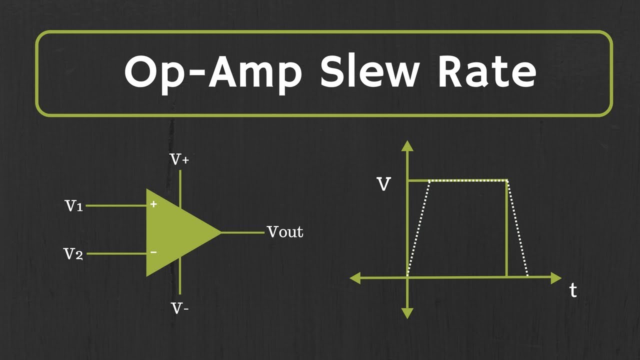
Op-Amp Slew Rate Explained (with Examples)
Показать описание
In this video, the slew rate of an Op-Amp has been explained with solved examples.
What is Slew Rate:
It defines the maximum rate at which the output of the op-amp can change. (How fast the op-amp is able to respond)
Unit of Slew Rate: V/us
Different Op-Amp has different slew rate and the value of slew rate varies from 0.1 V/us to 1000 V/us.
So, depending on the application the op-amp with specific slew rate needs to be selected which prevents the distortion of the output signal.
Causes of Slew Rate in Op-Amp:
The internal compensation capacitor in the Op-Amp is the main cause of slew rate in every Op-Amp.
The value of Slew rate depends on the value of this internal compensation capacitor and the charging or driving current.
Power Bandwidth of the Op-Amp:
The maximum frequency (for large signals) up to which there will not be any distortion in the output is known as the Power bandwidth of an op-amp.
This power bandwidth of the op-amp (slew rate limited maximum frequency ) is defined for the large signal (in volts), while the unity gain-bandwidth product is defined for the small signals (in mV).
If the input frequency is more than this maximum frequency, then the output signal will start getting distorted. And this kind of distortion in output is known as the slew rate induced distortion.
The timestamps for the different topics covered in the video is given below:
0:19 What is Slew Rate of an Op-Amp?
2:31 Causes of Slew Rate in Op-Amp
4:12 Effect of Slew Rate on Pulse input
7:46 Effect of Slew Rate on Sinusoidal Signal
10:21 Example 1
11:30 Example 2
The link to the related videos on the op-amp:
Introduction to Operational Amplifier:
Inverting Op-Amp:
Non-Inverting Op-Amp:
Op-Amp Integrator
Op-Amp Gain Bandwidth Product:
This video will be helpful to all student of science and engineering in understanding the slew rate of the op-amp.
Follow me on YouTube:
Follow me on Facebook:
Follow me on Instagram:
Music Credit:
 0:14:07
Op-Amp Slew Rate Explained (with Examples)
 0:04:17
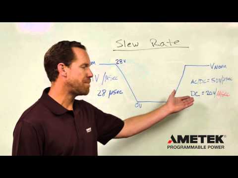
Operational Amplifier Slew Rate | Op Amp Slew Rate
 0:13:43
OpAmp Slew Rate vs. Rise Time
 0:15:01
OP-Amp Slew Rate With Examples and Solutions (Operational Amplifier)
 0:12:21
#1677 Op-amp Slew Rate
 0:10:03
Slew rate and bandwidth
 0:09:27
Amplifier slew rate
 0:15:32
#172: Basics of Op Amp Gain Bandwidth Product and Slew Rate Limit
 0:18:23
Op Amps: Slew Rate
 0:12:13
#1177 LM324 Op-amp Slew Rate
 0:02:30
Quiz # 202 (Op-Amp Slew Rate)
 0:08:02
Slew Rate vs Rise Time Measurements for Op Amps - Workbench Wednesdays
 0:01:44
What is Slew Rate?
 0:05:09
13. Slew Rate
 0:28:59
The Ultimate Op-Amp Comparison - Bandwidth, Slew Rate, Frequency Response, CMRR & More!
 0:02:28
Slew Rate of the Op-Amp (Quiz # 224)
 0:06:58
lab of slew rate of opamp
 0:12:49
Slew Rate in Opamp and Slew Rate Limiting
 0:12:02
Operational Amplifiers - Inverting & Non Inverting Op-Amps
 0:04:22
Slew Rate of Op Amps : A riddle on yet another bogus internet “teaching”
 0:09:42
Op Amp Slew Rate Considerations
 0:11:54
Op-Amp Limitations: Slew Rate & Full-Power Bandwidth
 0:05:48
calculating the slew rate
 0:00:24
slew rate of Op-Amps
Комментарии