filmov
tv
NRF24L01 Arduino Tutorial - Wireless Communication

Показать описание
NRF24L01 Arduino Tutorial - Wireless Communication
in this video we will see how to use the nrf24l01 to communicate wirelessly with 2 arduino boards
first we will have an overview of the features of the nrf24l01
then we will test the module with an example code
in example 1, we will send a Hello World Message over 1 board to another
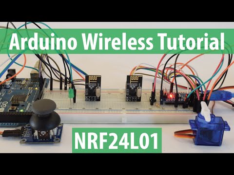
in the second example, we will control a led bulb on the uno using button on the nano,
and simultaneously control a servo motor on the nano using a joystick on the uno.
Code and Schematic Link:
the nrf24l01 is a rf transciever module, which means a single module works as both transmitter and receiver
it operates at a frequency of 2.4 ghz, which is one of the ISM band,
meaning it is open to use in most countries
the operating voltage is 1.9-3.6v, but the logic pins are 5v tolerant, so it can work with arduino
it has a baud rate or transfer rate of 250kbps to 2mbps
it has a maximum range of 100 metres, but works upto 60 metres in real conditions
it has 125 channels, meaning it can have a network of 125 transcievers at the same time
the power consumption during transmission is around 13mA
it uses SPI communication protocol
now lets see the connection
you have to connect the MOSI, MISO, SCK pins to the SPI pins of the arduino.
different arduinos have different pins for SPI. you can check the wiring diagram.
the SCN and CE pins can be connected to any digital pins of the arduino
we are using this IC socket base for the module, which has a power regulator and parallel capacitor
for safety.
you can have any input voltage in this socket base.
the last pin is an interrupt pin which is not used.
once we have connected the modules to the arduino, we can proceed to upload the code.
first we need to download the rf24 library. you can find the download link below.
we need to include the spi, nrf24l01 and rf24 libraries
we then define the ce and csn pins connected to the rf module.
and we define a 6 character address to the module, which is same of the receiver
you can find the codes in the description below.
now lets check the serial monitor to see the incoming message.
in our second example, we control a servo motor on the nano using a joystick on the uno,
and we control an led bulb on the uno with a button on the nano.
you can find the code for it in the descriotion below.
i have used my portable power supply to power the circuit as the servo consumes high current
as you can see i am able to control the servo and led.
hope you enjoyed the video. do let me know your views in the comment below.
also do check out these cool 3d Printers:
in this video we will see how to use the nrf24l01 to communicate wirelessly with 2 arduino boards
first we will have an overview of the features of the nrf24l01
then we will test the module with an example code
in example 1, we will send a Hello World Message over 1 board to another
in the second example, we will control a led bulb on the uno using button on the nano,
and simultaneously control a servo motor on the nano using a joystick on the uno.
Code and Schematic Link:
the nrf24l01 is a rf transciever module, which means a single module works as both transmitter and receiver
it operates at a frequency of 2.4 ghz, which is one of the ISM band,
meaning it is open to use in most countries
the operating voltage is 1.9-3.6v, but the logic pins are 5v tolerant, so it can work with arduino
it has a baud rate or transfer rate of 250kbps to 2mbps
it has a maximum range of 100 metres, but works upto 60 metres in real conditions
it has 125 channels, meaning it can have a network of 125 transcievers at the same time
the power consumption during transmission is around 13mA
it uses SPI communication protocol
now lets see the connection
you have to connect the MOSI, MISO, SCK pins to the SPI pins of the arduino.
different arduinos have different pins for SPI. you can check the wiring diagram.
the SCN and CE pins can be connected to any digital pins of the arduino
we are using this IC socket base for the module, which has a power regulator and parallel capacitor
for safety.
you can have any input voltage in this socket base.
the last pin is an interrupt pin which is not used.
once we have connected the modules to the arduino, we can proceed to upload the code.
first we need to download the rf24 library. you can find the download link below.
we need to include the spi, nrf24l01 and rf24 libraries
we then define the ce and csn pins connected to the rf module.
and we define a 6 character address to the module, which is same of the receiver
you can find the codes in the description below.
now lets check the serial monitor to see the incoming message.
in our second example, we control a servo motor on the nano using a joystick on the uno,
and we control an led bulb on the uno with a button on the nano.
you can find the code for it in the descriotion below.
i have used my portable power supply to power the circuit as the servo consumes high current
as you can see i am able to control the servo and led.
hope you enjoyed the video. do let me know your views in the comment below.
also do check out these cool 3d Printers:
 0:04:03
NRF24L01 Arduino Tutorial - Wireless Communication
 0:06:13
Arduino Tutorial: Arduino NRF24L01 Wireless Tutorial with Arduino Uno
 0:07:31
Arduino Wireless Communication – NRF24L01 Tutorial
 0:10:11
How the nRF24L01 Wireless Transceiver Module Works With Arduino.
 0:06:05
How To Use nRF24L01 with Arduino | Wireless Transmitter and Receiver using nRF24L01
 0:00:08
NRF24L01 Module with Arduino Code | NRF24L01 Arduino Projects | Arduino Wireless Communication
 0:00:23
Open Source Arduino Compatible RC Servo Remote NRF24L01 RF Module
 0:00:10
How to Make a Transmitter and Receiver using nRF24L01 | How to Use nRF24L01 #nrf24l01
 0:05:22
NRF24L01 Wireless Transceiver Tutorial | How to Use NRF24L01 with Arduino
 0:17:26
NRF24L01+ Setup With Arduino Nanos
 0:07:36
Arduino Wireless Joystick Shield Car nRF24L01 Transceiver
 0:00:46
NRF24L01 Wireless Module Explained in 30 Seconds! 🔥 With & Without Antenna #shorts
 0:12:52
Arduino NRF24L01 Joystick Controller Remote Transmitter
 0:00:45
Arduino Rover and Transmitter - NRF24L01 wireless comm modules - initial tests
 0:08:53
How to Connect nRF24L01 with Arduino Nano| Simple & Clear Guide
 0:00:22
ESP32 + NRF24L01 Wireless Control in Action! #ESP32 #Arduino #NRF24L01 #WirelessControl #TechShorts
 0:09:52
Arduino NRF24L01 Wireless Joystick Robot Car
 0:08:29
TUTORIAL: How to set up the NRF24L01 wireless transceiver Module - Arduino (Part 1 - Preparation)
 0:00:36
nRF24L01 Wireless Module | #electronics #arduino
 0:03:01
How To Use NRF24L01 With Arduino
 0:00:23
DIY 6 Channel RC Transmitter and Receiver using nRF24L01 and Arduno Nano #nrf24l01 #rcremote #rccar
 0:11:47
NRF24L01+ module line up, including SE8R01. Arduino
 0:01:36
Arduino NRF24L01 temperature transmitter
 0:11:40
ARDUINO NRF24L01 WIRELESS COCONUT HARVESTER MACHINE || Arduino Nrf24l01 transmitter-receiver
Комментарии