filmov
tv
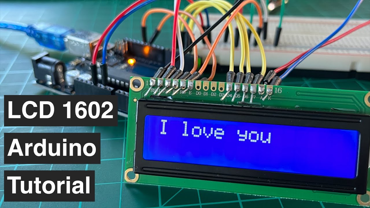
How to connect and program LCD 1602 to Arduino | Beginner's Step-by-Step Tutorial
Показать описание
Procedure/Steps in Connecting LCD 1602 to Microcontroller Board Arduino
00:19 Introduction: When to use Liquid Crystal Display (LCD)?
01:16 Step 01 Supply the breadboard with Arduino 5V Power and GND
01:33 Step 02 Connect the LCD's GND or VSS to the breadboard ground, and the LCD's VDD to the breadboard's power line.
01:39 Connect the LCD VDD pin to 5V
01:53 Step 04 Connect the LCD BackLight Anode pin to 5V power line in series with [220 ohms, 100K ohms] resistor.
02:13 Step 05 Connect LCD Cathode Pin to voltage low and control the LCD contrast V0 pin using potentiometer.
02:36 Step 06 Connect LCD Register Select RS pin to Arduino Digital Pin 12.
02:59 Step 07 Connect LCD Read/Write RW Pin to GND; Voltage High means Read and Voltage Low means Write.
03:09 Step 08 Connect LCD Enable Pin E to Arduino Digital Pin 11 to initiate LCD to receive instructions.
03:26 Step 09 Connect the last four LCD data bus ( D4, D5, D6, D7 ) to Arduino Digital Pins 5,4,3,2 in order. We use DB0 to DB7 for 8-bit data transfer. But since 4-bit data transfer is enough, we only use DB4 to DB7.
03:43 Step 10 To program Arduino, connect it to the computer.
03:59 How to check if Arduino is connected to Windows or detected by the laptop or computer using Device Manager
04:36 Step 11: Program the Arduino uno board to control or display Alphanumeric characters on the LCD.
04:43 LiquidCrystal header file
04:53 lcd object instantiation
05:09 lcd begin function
05:39 Select Arduino board type and COM PORT number in the IDE
05:43 Compile code by clicking the check or Verify button
06:16 lcd setCursor function
06:39 lcd print function
 0:06:17
How to connect and program encoder to Siemens PLC | TIA portal | S7-1200 | HSC High Speed Counter
 0:06:40
How to connect and program encoder to Schneider PLC | HSC High Speed Counter
 0:00:19
How to Connect Your Mobile Device to Your Windows Computer
 0:00:14
Control Your Phone From Your Laptop
 0:02:00
How To Connect And Program MK3 Steering Lock Emulator For Hyundai And KIA SMARTRA 2-3
 0:00:57
Can chatGPT Program an ESP32?
 0:04:22
Lesson #9 || How to connect program Encoder with Mitsubishi FX3U PLC GX developer || PLC Programming
 0:01:11
How to use the Program Assistant in the Home Connect app
 0:00:47
This AI Connects Over 7K+ Daily Use Apps
 0:09:13
How to connect a R Program to MySQL Server Database ?
 0:03:57
How to Connect and Program for 6 P3 LED Poster Screen
 0:02:28
How to: reset, pair/program and connect your XR16 xfinity flex remote
 0:00:59
P8 Drone How To Successfully Bind & Connect To The Camera
 0:07:00
How To Connect Your Google Credentials to n8n (Step-by-Step Tutorial)
 0:00:55
Setting up an audio interface
 0:02:48
How to connect and program a PLC with PLC Next Engineeer Software , PLC Tutorial Part-3
 0:15:42
Program 2: How to connect two PC's and switch
 0:05:41
Connect Robot and Run Program
 0:01:00
How To Connect A Guitar To A Computer
 0:00:33
How to Connect Verizon Remote to TV | Verizon Remote Pairing Guide | Program Verizon Remote
 0:08:01
Connect & Program an OLED Stats Display on Raspberry Pi OS Bookworm
 0:06:04
How to Connect SIEMENS SIPROTEC 7SJ Protection Relay with DIGSI Program
 0:00:31
Change DNS in Windows
 0:02:43
How to Program/Set up/ Connect Philips Universal Remote Control to TV (Step by Step)
Комментарии