filmov
tv
IoT based Data Monitor and Alert System using Bolt IoT module and ESP8266

Показать описание
Monitor the Temperature, Humidity, Air Quality, LPG, Carbon Monoxide, Smoke and detect Fire in the surrounding environment. It can send alert to Telegram based on the limit set in the telegram app using telegram bot. Telegram app can also be used to monitor the values and download the CSV File from the Bolt IoT Cloud using the date and time entered by the user. The data can be monitored and visualized on the Bolt IoT Cloud Platform. Web Server can also be used to monitor and change the threshold values of the parameters.
Things used in this project
Hardware components
Bolt WiFi Module
Hardware setup
Step 1) Connect the DHT-22 Temperature and Humidity Sensor with the NodeMCU ESP8266 and Bolt IoT Module as per the following:
Vcc and Gnd (DHT-22) is connected to 3.3 V and Gnd (Bolt IoT Module)
Data (DHT-22) is connected to D5 (NodeMCU ESP8266)
Step 2) Connect the MQ-135 Air Quality Sensor with the NodeMCU ESP8266 and Bolt IoT Module as per the following:
Vcc and Gnd (MQ-135) is connected to 3.3 V and Gnd(Bolt IoT Module)
A0 (MQ-135) is connected to Channel 1 (CD4051 IC)
Step 3) Connect the MQ-2 LPG, Carbon Monoxide and Smoke Sensor with the NodeMCU ESP8266 and Bolt IoT Module as per the following:
Vcc and Gnd (MQ-2) is connected to 3.3 V and Gnd (Bolt IoT Module)
A0 (MQ-2) is connected to Channel 0 (CD4051 IC)
Step 4) Connect the Fire Sensor with the NodeMCU ESP8266 and Bolt IoT Module as per the following:
Vcc (Fire sensor) is connected to 3.3 V (Bolt IoT Module)
Gnd (Fire sensor) is connected to Gnd (Bolt IoT Module)
D0 (Fire sensor) is connected to D0 (NodeMCU ESP8266)
Step 5) Connect each 7 LEDs to 150 Ohm Resistor which are then connected QA, QB, QC, QD, QE, QF, QG of SN74HC595 IC.
Step 6) Connect the 20×4 LCD with I2C module with the NodeMCU ESP8266 and Bolt IoT Module as per the following:
Vcc (I2C Module) is connected to 5 V (Bolt IoT Module)
Gnd (I2C Module) is connected to Gnd (Bolt IoT Module)
SCL (I2C Module) is connected to D1 (NodeMCU ESP8266)
SDA (I2C Module) is connected to D2 (NodeMCU ESP8266)
Step 7) Connect the SN74HC595 IC with the NodeMCU ESP8266 and Bolt IoT Module as per the following:
Vcc (SN74HC595 IC) is connected to 3.3 V (Bolt IoT Module)
SRCLR’ (SN74HC595 IC) is connected to 3.3 V (Bolt IoT Module)
Gnd (SN74HC595 IC) is connected to Gnd (Bolt IoT Module)
OE’ (SN74HC595 IC) is connected to Gnd (Bolt IoT Module)
SER (SN74HC595 IC) is connected to D6 (NodeMCU ESP8266)
RCLK (SN74HC595 IC) is connected to D7 (NodeMCU ESP8266)
SRCLK (SN74HC595 IC) is connected to D8 (NodeMCU ESP8266)
Step 8) Connect the Buzzer with the NodeMCU ESP8266 and Bolt IoT Module as per the following:
Vcc (Buzzer) is connected to 3.3 V (Bolt IoT Module)
Gnd (Buzzer) is connected to Gnd (Bolt IoT Module)
I/O (Buzzer) is connected to D3 (NodeMCU ESP8266)
Step 9) Connect the CD4051 IC with the NodeMCU ESP8266 and Bolt IoT Module as per the following:
Vdd (CD4051 IC) is connected to 3.3 V (Bolt IoT Module)
Gnd, Input B, Input C, Inhibit, Vss, Vee (CD4051 IC) is connected to Gnd (Bolt IoT Module)
Common in/out (CD4051 IC) is connected to A0 (NodeMCU ESP8266)
Input A (CD4051 IC) is connected to D4 (NodeMCU ESP8266)
Step 10) Bolt IoT Module with NodeMCU ESP8266 as per the following:
5V (Bolt IoT Module) is connected to 5 V (LCD I2C Module)
3.3V(Bolt IoT Module) is connected to 3.3V (NodeMCU ESP8266)
Gnd (Bolt IoT Module) is connected to Gnd (NodeMCU ESP8266)
RX (Bolt IoT Module) is connected to TX (NodeMCU ESP8266)
TX (Bolt IoT Module) is connected to RX (NodeMCU ESP8266)
Before uploading the code, add the following libraries:
 0:00:23
IoT Based Patient Health Monitor System using Blynk and ESP32 #esp32 #max30100 #ds18b20 #dht11
 0:09:35
IoT based Smart Energy Meter using ESP32 & Google Sheet | Google Spreadsheet
 0:00:15
IOT based Patient Health monitoring system with GSR sensor #arduino #project #iot #innovation
 0:03:26
ESP8266/ESP32 based Patient Health Monitoring System
 0:05:09
AWS Solutions: Real-Time IoT Device Monitoring with Kinesis Data Analytics
 0:10:06
IoT Based Indoor Air Quality Monitoring Using BME680 and ESP8266
 0:08:01
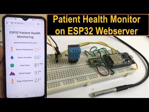
IoT Based Patient Health Monitoring System using ESP32 Web Server
 0:00:11
How to make IOT based Affordable Home Security System with message alert
 0:11:18
Real-Time Streaming with Azure Services - part1 | Stream Analytics & Event Hubs Explained
 0:00:12
Radar monitoring with ESP32, MQTT and node-red
 0:00:14
Read and Display Temperature Data on Raspberry Pi Pico 2 Using MicroPython!
 0:12:00
IoT based Low-cost ECG & Heart monitoring system with ESP32 and Ubidots Platform
 0:00:16
RFID Attendance System using ESP32 and Google Sheet #rfid #iot #esp32project
 0:08:56
11. IoT🌐 Based Motor Monitoring & Control System | Current | Voltage | RPM🛞 | Temp🌡️| Control | ...
 0:07:20
IoT Based Solar Power Monitoring System with ESP32 & ThingSpeak Server
 0:10:30
An IoT Based Real-Time Environmental Monitoring System Using Arduino and Cloud Service
 0:00:24
Smart irrigation system with Arduino UNO R4 WIFI board #sritu_hobby #sritu_hobby @sritu_hobby
 0:00:24
Amazing Arduino IoT Project🤯
 0:00:08
IoT based health monitoring system
 0:00:18
ESP32 IoT Project- Simplest! #esp32 #iot #arduino
 0:09:25
IoT Based Drinking Water Quality Monitoring System with ESP32
 0:00:11
Cloud-Based DIY Plant Monitoring System with Arduino #arduino #IoT #technology #engineering
 0:04:34
MODBUS RS485 4G IOT Gateway
 0:18:03
IoT Sensor Monitoring Roadmap - Introducing the Hawk IoT Datalogger
Комментарии