filmov
tv
Devil is in the Details (Lean of Peak Aviation)

Показать описание
Investigating and proving what caused a major control system failure in my Sonex Onex.
 0:03:23
The Devil is in the Details
 0:03:54
The Devil Is In The Details
 0:02:05
Dateline Episode Trailer: The Devil's in the Details | Dateline NBC
 0:01:40
The Devil is in the Details - An Introduction to our new series!
 0:06:19
Semihedonist - Devil is in the Details
 0:04:42
Idiom: The devil is in the details.
 0:02:58
Mac Ayres - The Devil's In The Details (feat. Castelluzzo)
 0:35:05
MANIFEST AS GOD, NOT AS THE DEVIL. 'The Devil is in the details.'
 0:02:32
O DIABO MORA NOS DETALHES
 0:03:38
Lee DeWyze - Devil In The Details - Official Video
 0:27:30
The Devil is in the Details
 0:03:40
Marnie Stern - The Devil is in the Details (from This Is It...)
 0:00:30
the devil is in the details
 0:00:47
THE DEVIL IS IN THE DETAILS 🔴😈⚫️ | #Shorts
 0:01:01
The Devil Is In the Details 🍎🐍
 0:00:38
Devil is in the details Meaning
 0:02:43
the devil's in the details
 0:03:23
The Devil is in the details
 0:03:24
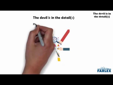
English Tutor Nick P Proverbs (120) The Devil is in the Details
 0:03:22
The Devil Is In The Details!!
 0:07:57
The Devil is in the Details
 0:00:12
The Devil is in the Details 😈
 0:02:28
Steve Jobs leadership lessons: The devil is in the details | Walter Isaacson | WOBI
 0:12:54
The devil is in the details
Комментарии