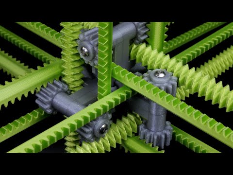
Six axis racks

preview_player
Показать описание
A kinetic sculpture in which 12 sticks with 24 racks interact with 12 gears.

Рекомендации по теме
Комментарии
Автор

If a pair of sticks had a diagonal connecting bar on only one side of the hub, making a sort of U shape, the other pair parallel with it could have a connecting bar on the other side of the hub. It would still be possible to pull the sticks out in one direction, but there would be a “safe” direction where it collided with the hub, and there would effectively be half as many stick components to get lined up in sync.

SkeletalPhoenix
Автор

this seriously looks like one of those satisfying looping animations

xaracen
Автор

The way the sticks mutually hold each other in place immediately makes me think of the Borromean Rings.

zh
Автор

What comes to mind for easier assembly is:
1. Make a jig which can hold all the racks and the core in the right positions, but doesn't touch the gears.
2. Assemble the core puzzle.
3. Put all the parts in the jig except for the gears.
4. Slide the gears onto their axles.
That way, all the racks can be put into their central position without any constraints, rather than needing to start in the “just falling out” position all at once.

kevinpreid
Автор

I can't even comprehend the sticks holding each other around the core, forget about the movement! so cool!

purplelord
Автор

5:08

Different Idea: you can have the driving rack have a waffle iron pattern and the driven racks can both be driven.

Think of the driven racks as tools that carve tracks out of the driving rack, if you carve both patterns out of the driving rack it will only have little parallelogram nubs that don't interface with the whole sliding surface, but it will be able to go both ways

dundeedideley
Автор

You could connect the axial pairs by using concentric rings, just set the rings on the inside or outside of the pair and have mounting tabs, this would allow for a full range of motion. Stemming from this, the concentric rings could also have a guide pin that sits on the outer face of the rings with a pole that sits on the curved surface of the core, where the axle for the gears sits, this would help for assembly. For assembly, the various constraints are what make this easy, the system is constrained to where all centerpoints align, and the gears just slot into place, the guide pins are a temporary constraint whereas the gears are a permanent constraint.

For clarification on the concentric rings: Say the square of rods is a base circle. One pair of rods would get a larger concentric circle, the other pair gets a smaller concentric circle, both with mounting tabs for the pair of rods they connect to. For example, axis positive would get a larger circle, axis negative would get a smaller circle; though, personally, I think each pair should get both sizes of rings on the two ends, which could be further used as an endstop against the core. The guide pin would have a flange that seats on both circles at the same time, thus constraining them to the same centerpoint position; and in combination with the guide pin's rod seating on the core, this constrains the axial pair's centerpoints to the core's centerpoint.

Let's look at one set of rods, say the X-axis. The core constrains the rods in the Y and Z axes, allowing free movement within the X-axis. The concentric rings will constrain the positive and negative pairs of the four rods, which this later becomes redundant with the installation of the gears. The guide pin will constrain the X-axis position of both of these pairs; at least as a soft constraint with one pin, and a hard constraint with two pins, but really only one is needed. Repeat this for the Y and Z axial pairs. The installation of the gears would now constrain the rods to the core, the two opposed axial pairs together, and an axial rod to its perpendicular neighbor, thus constraining everything together. The original product already had this final constraint, but with a more difficult assembly, but mimicking these constraints during assembly makes the process easier, and as a coincidental byproduct the system that binds two rods together is also usable for setting up the assembly constraints.

xaytana
Автор

5:34 Can't you have diagonal racks on both sides of a stick to achieve direct contact opposite motion?

donotneedahandle
Автор

7:15 "But I do want to talk about the core on its own, so I guess I have to…"

I see you have not yet discovered the magic of making two of them!

columbusmyhw
Автор

Engendering students really need this as part of their core continuum.

johnwenzel
Автор

Here's what worked for me! First, mark the center of each rack on the back side. Then, starting with a bare hub (no pinions), arrange four racks and put a rubber band around each end of each set to hold them to the hub. Then again with another set of 4 and rubber bands. Get them all approximately centered; they don't have to be in exactly the right position or rotation, just close. Then choose a pinion that will contact three of the racks and insert it (with the bolt), careful to center each of the 3 racks it contacts as you do. Repeat for the opposing pinion, then the other two that contact the racks placed so far. Repeat one more time with the remaining four racks and two pinions. I'm not saying it's easy, but it was relatively straightforward.

EDIT: Also, thanks for the cool design, and informative video! I'm sure it will be a great conversation piece!

weeeeelaaaaaah
Автор

Great as always! To connect 2 rods you could probably add a brace that does not connect straight across, but in an arch that skips over the other rods

zeugundso
Автор

lovely - i reached for my star burr puzzle and pulled it apart as you did in your video - so thanks for naming that wooden puzzle of mine that i guess me dad bought decades ago - but also - i now have to remember how to put the star burr puzzle back together again - x

longcat
Автор

Wow, this is absolutely fascinating! I can't think of any practical use cases in my head right now (though there are probably a good amount), but I'm thinking some implementation into a crazy CNC based system for experimental manufacturing!

aiyushg
Автор

I love your videos. Great videography, wonderful explanations of how things work. It's both eye and brain candy.

supergiantbubbles
Автор

5:22 On the lower single stick you could change it to a diamond pattern where it is both diagonals cut out of it. You could also add a connector bar to each end of only one pair of sticks per side and it would also stop the sticks from falling out while allowing the ends to move past each other (add the bar to both ends of the pair moving one direction along the x axis but not the other parallel pair of sticks that moves the opposite direction and same for y and z axis).

SilvrDragon
Автор

I find all of these so mechanically pleasing.
To assemble,
line up all the racks on the core with toothless gears/wheels so everything slides easy,
tape racks to hold the shape,
and swap out the wheels for gears 1 by 1 meshing teeth as you go.

lukekamrath
Автор

To stop the racks from falling out of the core you could make little screw on caps for the ends of the racks that would be too big to get pulled out, similar to how the gears are mounted but with a flange rather than a gear.

conorstewart
Автор

There is a way of having this be a rack-rack interaction: Just have one of the racks have a pattern of a diamond lattice that you get when you do a union of the two diagonal rack patterns.

Dom-Nom-Nom
Автор

I feel like I'm watching secrets of the universe while watching this channel

AaaBbb-lmqw