filmov
tv
ESP32-C3 based Smart Door/Window sensor | DEEP SLEEP 30nA? | Long battery life 5/10 years

Показать описание
The goal of this project is to design a smart door/window sensor reducing power consumption(in deep sleep/standby) with a custom power latch. Optimizing the deep sleep power consumption of battery-powered smart devices ensures a long battery life cycle.
The current was measured with Nordic's power profiler kit, knowing that the current measured is less than the measurement range of this power profiler. I did several tests to verify the accuracy of the data. In any case the accuracy of the data, the consumption would be less than 200nA and this is a very good result considering that a similar device at a power consumption of 6-8uA.
Interesting projects about the topic:
Topics/projects covered in this video:
IoT power consumption:
Links:
🎶 Tracks:
"Punch Deck - Neon Underworld" is under a Creative Commons (CC BY 3.0) license.
@punchdeck
 0:11:47
ESP32-C3 based Smart Door/Window sensor | DEEP SLEEP 30nA? | Long battery life 5/10 years
 0:00:30
DIY smart door/window sensor with ESP32-C3 #pcb #pcba #iot #sensors #esp32 #electronics #design
 0:04:33
My Door Sensor (Revised Design) Breakdown and Upgrades
 0:00:20
ESP32C3 Smart door sensor #iot #electronics #engineering #pcb #design #pcba #soldering #diy #esp
 0:05:31
Contact Sensor 3 - an ESP8266 Door & Window Sensor
 0:17:57
ESP8266 as Window Sensor with years of battery life
 0:00:51
I designed a smart device with OBJEX Link #iot #engineering #electronics #esp32 #3dprinting #sensor
 0:06:07
ESP32 Door Sensor
 0:00:22
What engineering students actually do in labs 💀 #electronics #arduino #engineering
 0:08:21
I've built a Smart Home device with ESP32-C3 | OBJEX Link based | Part 1
 0:01:00
I made a DIY $6 ESP32-C3 module and it drives NeoPixels like a boss!
 0:00:29
Difference between Osram Standard, Night Breaker Laser, Cool Blue Advance and Fog Breaker
 0:00:12
2023 Tesla MODEL Y Performance ⚠️ BUT Did You See… 🤤😘 #Shorts #Short #Tesla #teslamodely
 0:11:04
New Sonoff Basic R4 ESP32-C3 and Bonus mmWave Zigbee Sensor
 0:00:17
Control Appliances using SmartWatch 🤯🤯 | ESP32 Smart watch | T-Watch 2020 v3 #esp32 #iot #twatch2020...
 0:00:16
Describe your perfect vacation. #philippines #angelescity #expat #travel #filipina #phillipines
 0:12:21
453 Use your Arduino and ESP32/ESP8266 from your Smartphone. No Cloud! (RemoteXY)
 0:15:42
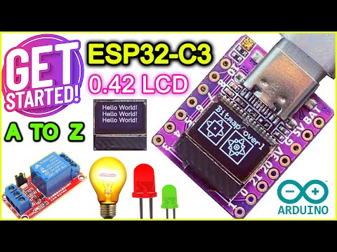
Getting Started With ESP32-C3 Development Board || Tiny WiFi & BLE IoT Board With 0.42-inch Disp...
 0:00:26
Ich fahre Dich überall hin! #davidbost #motorrad #gehtsteil #shorts
 0:08:55
ESP32 HomeKit Tutorial | HomeSpan
 0:00:25
ESP32-C3 Simple end to end #iot in 10 minutes #short
 0:13:38
esp32 home automation DIY with iOS16 Apple Homekit
 0:00:28
Making flash memory from SD Card
 0:00:57
🤷♂️How I Pranked my Neighbour !!!😜
Комментарии