filmov
tv
Arduino Countdown Timer using the easier to find MAX7219 module!

Показать описание
Let's remake the Countdown timer, this time using the easier to find: 8Bits 7 Segments module controlled by the popular MAX7219 chip!
 0:00:13
Arduino countdown timer
 0:19:17
Arduino Adjustable Countdown Timer
 0:00:24
Arduino countdown timer demo (use LED matrix8x8 4pcs)
 0:01:03
Arduino 7 segments count down timer with buzzer
 0:14:59
Countdown timer with Arduino #arduino #countdown
 0:08:54
4-Digit Countdown Timer (in minutes and seconds)
 0:04:51
Arduino 4-Digit 7-Segment Display Countdown Timer w/Passive Buzzer
 0:06:34
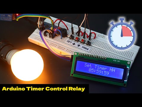
Arduino Timer Control Relay Devices
 0:16:09
Arduino countdown timer
 0:00:38
Escape room Arduino controllable countdown timer
 0:01:59
Arduino Count Down Timer LCD Screen Hours,Minute,Second -TEST PROJECT
 0:00:15
Arduino Uno 4-Digit 7-Segment Timer Counter
 0:01:53
Countdown Timer Using Arduino Multi-function Shield
 0:00:48
Arduino Countdown Timer with TM1637
 0:04:07
Arduino Minute Count Down Timer On off Relay using Rotary encoder & TM1637 display
 0:04:29
How To Make Arduino Countdown Timer with LCD || MSD
 0:01:34
countdown Timer using Arduino
 0:07:32
Tiny Project - Countdown timer (Attiny85 , 64x32 OLED and datacute library)
 0:00:40
Arduino Uno Countdown Timer with 2 Buttons (Start&Pause)
 0:00:11
How to do a countdown timer using the arduino uno
 0:03:12
Count Down timer using Arduino and TM1637 display module
 0:01:49
Arduino countdown timer using rotary encoder, oled display and 12v latch
 0:03:06
ELEGOO Project: 3D Printed Arduino Countdown Timer
 0:03:56
COUNTDOWN TIMER using Arduino nano, OLED Display, Buzzer, and Buttons (DEMO only) Video #14
Комментарии