filmov
tv
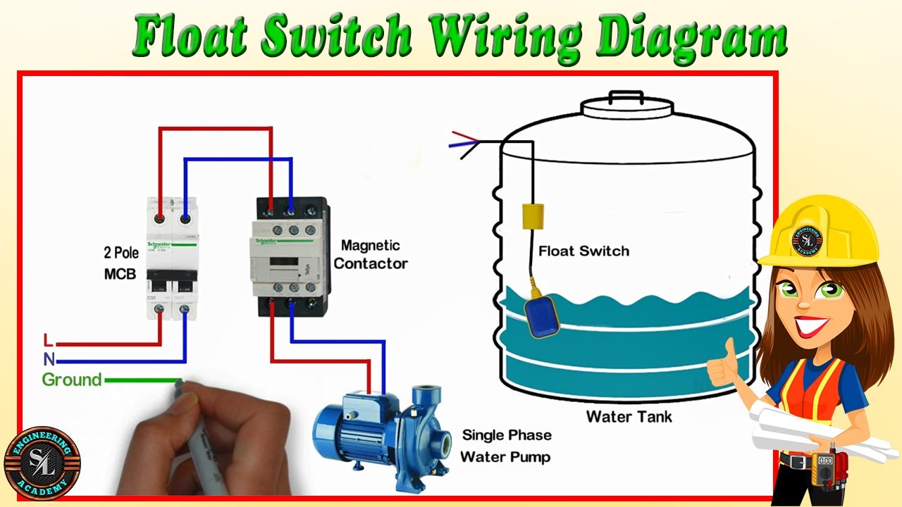
Float Switch Wiring Diagram for Water Pump/ How to Make Automatic On-Off Switch for Water Pump
Показать описание
A float switch is a mechanical switch that floats on top of a liquid surface. As the liquid level goes up or down, it moves vertically with the liquid level. This is a type of level sensor and this device is used to detect the level of liquid within a tank. And also float switch may be used to control a pump, as an indicator, an alarm, or to control other devices.
In this video, I have explained about float switch wiring connection to control a water pump.
What is a float switch?
A float switch detects the level of a liquid in a tank. Based on the water level, it will open or close an electrical circuit generally used to pump water in or out of the tank.
How to work a float switch?
A float switch moves with the liquid level up and down vertically. An internal mechanical switch opens or closes an electrical circuit with gravity. Therefore, the electrical circuit can turn on/off equipment, like a water pump.
What does a float switch do?
A float switch monitors the level of a liquid in a tank. It then opens or closes an electrical circuit based on the liquid level and wiring to control external components.
How to install a float switch?
A float switch is installed in a liquid tank. Firstly, a pre-set level is made and can be done with a counterweight. Then, based on a normally open or closed wiring configuration, it will open or close the electrical circuit based on its movement up or down with the liquid level.
How to wire a float switch?
A float switch is wired in either the normally open or normally closed position. A normally open position is open when down (low liquid level) and a normally closed position is closed when down. The open/closed position refers to the electrical circuit.
If you have any questions about float switch wiring, please comment below the video. I will answer your questions.
Thanks for watching this video.
PLEASE SUBSCRIBE THIS CHANNEL FOR MORE VIDEOS.
💻Connect with SL Engineering Academy
More video
Complete Electrical House Wiring / Single Phase Full House Wiring Diagram
Single Phase House Wiring Diagram / Single Phase DB Wiring
Two Way Switch Connection / How to Wire 2 Way Light Switch / Starecase Wiring with 2 Way Switch
Automatic Changeover Switch for Generator / Automatic Transfer Switch / ATS (With Circuit Diagram)
DOL Starter Connection with Indicator | 3 Phase Direct On Line Starter/ Explain with Circuit Diagram
Star Delta Starter for 3 Phase Induction Motor / Star Delta Connection
Float Switch Wiring Diagram for Water Pump/ How to Make Automatic On-Off Switch for Water Pump
Float Switch Connection with Auto & Manual Selector Switch for Single Phase Water Pump
How to Wire Ceiling Fan and Fan Regulator / Ceiling Fan Connection / Fan Regulator Connection
3 Phase Distribution Board Layout and Wiring Diagram
Earth Leakage Relay - ELR / How to Wire ELR & CBCT with MCCB / Working Principle of ELR
Single Phase Split Type Air Conditioner(AC) Indoor & Outdoor Wiring Diagram/ How to Wire Split AC
 0:03:25
Float Switch Wiring Diagram for Water Pump/ How to Make Automatic On-Off Switch for Water Pump
 0:03:06
Float Switch Wiring Diagram For Water Pump
 0:04:09
float switch wiring diagram for water pump
 0:03:28
Float switch wiring diagram for water pump | How float switch works
 0:04:57
float switch wiring practical video
 0:02:52
FLOAT SWITCH WIRING DIAGRAM
 0:02:48
float switch wiring diagram for water pump
 0:00:55
Float Switch Wiring without magnetic contactor
 0:10:04
250 Volts Float Switch Sensor for Water Level Controller in hotel
 0:00:15
float switch connection
 0:00:11
Unveiling the Secret to Making Float Sensor Wiring Simple!
 0:00:15
float switch wiring diagram for water pump
 0:00:20
how to connection water tank float switch
 0:00:14
How to float switch connection with motor starter | water level control #shorts #shortsvideo #viral
 0:01:38
float switch wiring diagram for water pump | How float switch works
 0:00:20
Float Switch for Water level controller#float#switch#connection#wiring#shorts#viral
 0:00:47
3 Phase water pump Float Switch Connection. Wiring Diagram. CSQ Float Switch.
 0:01:32
Float Switch Connection Auto And Manual | Engineers CommonRoom ।Electrical Circuit Diagram
 0:00:16
Step-by-Step Float Switch Connection for Optimal Pump Efficiency
 0:00:16
Two float switch and two water tank connection diagram. Electric24 Tech
 0:04:16
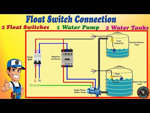
How to Connect 2 Float Switches to Water Pump / Float Switch Connection Explain with Circuit Diagram
 0:04:06
Submersible pump float switch wiring diagram
 0:03:38
HOW TO INSTALL FLOAT SWITCH FOR WATER PUMP
 0:00:19
how to float switch connection with motor starter ! water level control #shorts #shortsfeed
Комментарии